AAWSAP DIRD, Materials for Advanced Aerospace Platforms, January 2010
DOW-UAP-D120 · page 15 of 27
Text
This text came with the file. It may have mistakes. When the text and the image disagree, the image is right.
UNCLASSIFIED//Pelt OfFI61Ak WIiii ,u1L¥
considered in light of the thermal stresses that were certain to develop in a large
structure placed in the fluidized bed.
Reusable Single-Stage-to-Orbit Vehicles
A reusable single-stage-to-orbit (SSO) vehicle will require metallic materials for the TPS
and for much of the other hot structure. This will be challenging from the standpoint of
an empty vehicle weight. With the exception of military applications, which are outside
the scope of this document, empty vehicle weight is a critical metric because every
additional pound of empty weight reduces the payload by the same amount (assuming
a fixed propulsion capability). As mentioned earlier, the key to a lightweight vehicle is
the use of design methods that integrate the TPS and the load-bearing structure to
minimize structural redundancy and single-function structure (for example, a TPS that
is not load bearing). Achieving this goal will require new design paradigms that
incorporate true synthesis of new structural concepts. In reality, such designs can be
completed only if they are based on a detailed set of mission requirements, including
the number of missions and expectations for turnaround time between missions.
Furthermore, operational parameters such as the value of inserting a pound of payload
into orbit are needed to bound the cost of the initial vehicle and the maintenance cost
per mission (translated into cost per pound of payload). Absent such specific data, the
following discusses possibilities for materials systems that can enable a reusable SSO
vehicle. It is perhaps more efficient to discuss these materials according to their
principal capability and the anticipated temperature regime in which they can be used
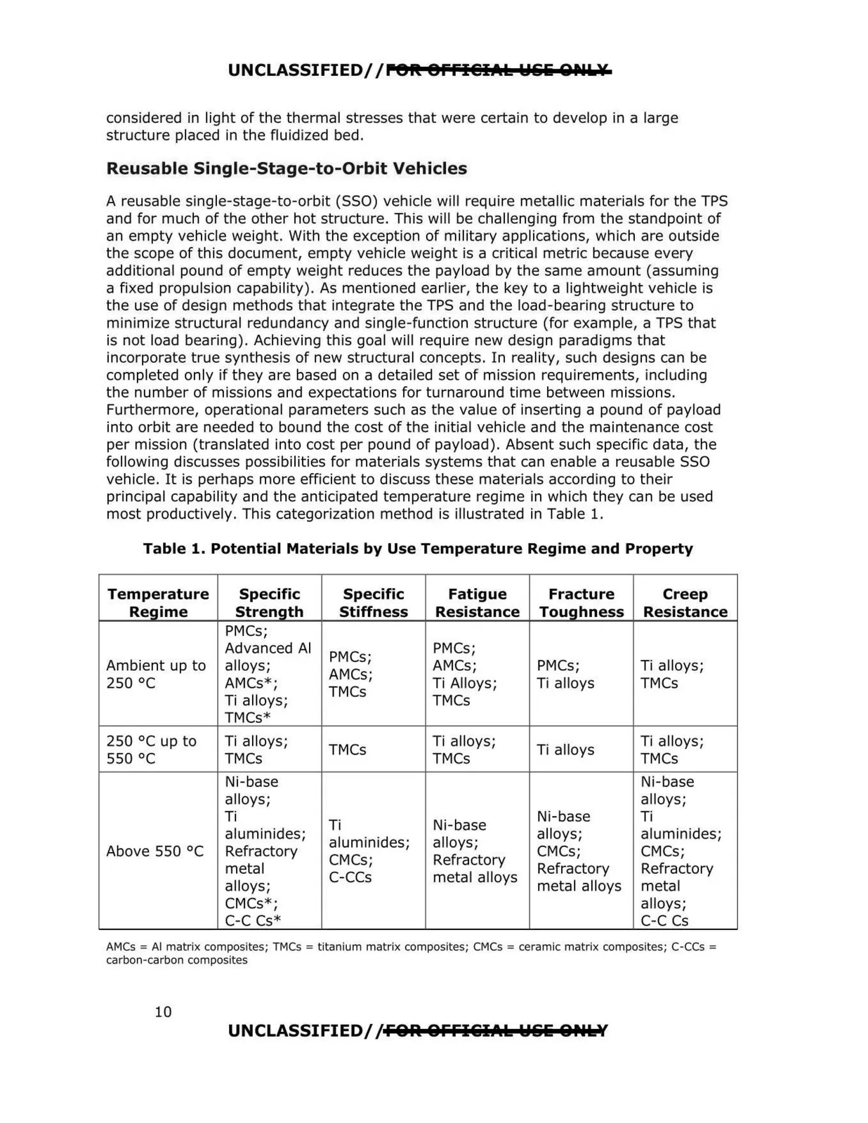
most productively. This categorization method is illustrated in Table 1.
Table 1. Potential Materials by Use Temperature Regime and Property
Temperature
Specific
Specific
Fatigue
Fracture
Creep
Regime
Strength
Stiffness
Resistance
Toughness
Resistance
PMCs;
Ambient up to
250 °C
Advanced Al
alloys;
AMCs* ;
Ti alloys;
PMCs;
AMCs;
TMCs
PMCs;
AMCs;
Ti Alloys;
TMCs
PMCs;
Ti alloys
Ti alloys;
TMCs
TMCs*
250 °Cup to
550 °C
Ti alloys;
TMCs
TMCs
Ti alloys;
TMCs
Ti alloys
Ti alloys;
TMCs
Above 550 °C
Ni-base
alloys;
Ti
aluminides;
Refractory
metal
alloys;
CMCs* ;
C-C Cs*
Ti
aluminides;
CMCs;
c-ccs
Ni-base
alloys;
Refractory
metal alloys
Ni-base
alloys;
CMCs;
Refractory
metal alloys
Ni-base
alloys;
Ti
aluminides;
CMCs;
Refractory
metal
alloys;
C-C Cs
AMCs = Al matrix composites; TMCs = titanium matrix composites; CMCs = ceramic matrix composites; C-CCs =
carbon-carbon composites
10
UNCLASSIFIED//FOR. OFFl&IAk WIiii &Ptklf