AAWSAP DIRD, Pulsed High-Power Microwave Source Technology, January 2010
DOW-UAP-D121 · page 27 of 37
Text
This text came with the file. It may have mistakes. When the text and the image disagree, the image is right.
UNCLASSIFIED//POil Offl61Ak Wlilii ,u1L¥
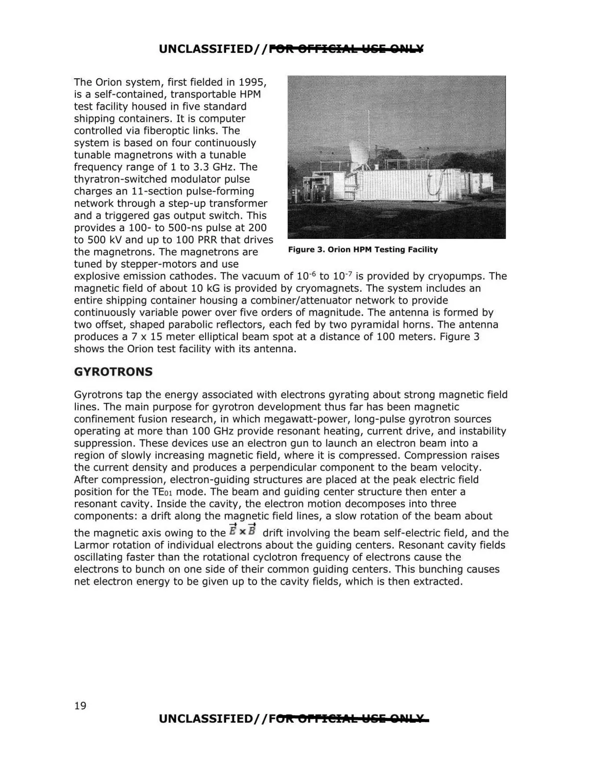
The Orion system, first fielded in 1995,
is a self-contained, transportable HPM
test facility housed in five standard
shipping containers. It is computer
controlled via fiberoptic links. The
system is based on four continuously
tunable magnetrons with a tunable
frequency range of 1 to 3.3 GHz. The
thyratron-switched modulator pulse
charges an 11-section pulse-forming
network through a step-up transformer
and a triggered gas output switch. This
provides a 100- to 500-ns pulse at 200
to 500 kV and up to 100 PRR that drives
the magnetrons. The magnetrons are
Figure 3. Orion HPM Testing Facility
tuned by stepper-motors and use
explosive emission cathodes. The vacuum of 10-6 to 10-7 is provided by cryopumps. The
magnetic field of about 10 kG is provided by cryomagnets. The system includes an
entire shipping container housing a combiner/attenuator network to provide
continuously variable power over five orders of magnitude. The antenna is formed by
two offset, shaped parabolic reflectors, each fed by two pyramidal horns. The antenna
produces a 7 x 15 meter elliptical beam spot at a distance of 100 meters. Figure 3
shows the Orion test facility with its antenna.
GYROTRONS
Gyrotrons tap the energy associated with electrons gyrating about strong magnetic field
lines. The main purpose for gyrotron development thus far has been magnetic
confinement fusion research, in which megawatt-power, long-pulse gyrotron sources
operating at more than 100 GHz provide resonant heating, current drive, and instability
suppression. These devices use an electron gun to launch an electron beam into a
region of slowly increasing magnetic field, where it is compressed. Compression raises
the current density and produces a perpendicular component to the beam velocity.
After compression, electron-guiding structures are placed at the peak electric field
position for the TE01 mode. The beam and guiding center structure then enter a
resonant cavity. Inside the cavity, the electron motion decomposes into three
components: a drift along the magnetic field lines, a slow rotation of the beam about
........
the magnetic axis owing to the 'H x 'B drift involving the beam self-electric field, and the
Larmor rotation of individual electrons about the guiding centers. Resonant cavity fields
oscillating faster than the rotational cyclotron frequency of electrons cause the
electrons to bunch on one side of their common guiding centers. This bunching causes
net electron energy to be given up to the cavity fields, which is then extracted.
UNCLASSIFIED/ /FOR. errl@IAI:. Wlilii QIUL¥
19