AAWSAP DIRD, Pulsed High-Power Microwave Source Technology, January 2010
DOW-UAP-D121 · page 32 of 37
Text
This text came with the file. It may have mistakes. When the text and the image disagree, the image is right.
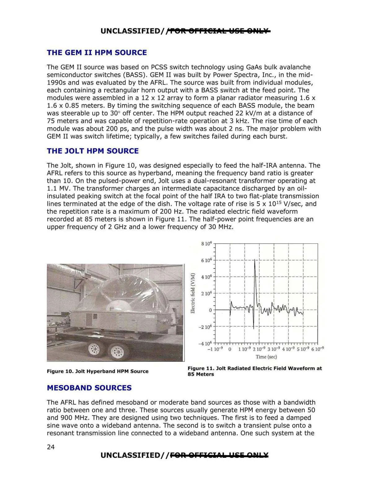
__ _ UNCLASSIFIED//re1t Offl@IAL lel§li 8PUs:lf THE GEM II HPM SOURCE The GEM II source was based on PCSS switch technology using GaAs bulk avalanche semiconductor switches (BASS). GEM II was built by Power Spectra, Inc., in the mid 1990s and was evaluated by the AFRL. The source was built from individual modules, each containing a rectangular horn output with a BASS switch at the feed point. The modules were assembled in a 12 x 12 array to form a planar radiator measuring 1.6 x 1.6 x 0.85 meters. By timing the switching sequence of each BASS module, the beam was steerable up to 30° off center. The HPM output reached 22 kV/mat a distance of 75 meters and was capable of repetition-rate operation at 3 kHz. The rise time of each module was about 200 ps, and the pulse width was about 2 ns. The major problem with GEM II was switch lifetime; typically, a few switches failed during each burst. THE JOLT HPM SOURCE The Jolt, shown in Figure 10, was designed especially to feed the half-IRA antenna. The AFRL refers to this source as hyperband, meaning the frequency band ratio is greater than 10. On the pulsed-power end, Jolt uses a dual-resonant transformer operating at 1.1 MV. The transformer charges an intermediate capacitance discharged by an oil insulated peaking switch at the focal point of the half IRA to two flat-plate transmission lines terminated at the edge of the dish. The voltage rate of rise is 5 x 10¹⁵ V/sec, and the repetition rate is a maximum of 200 Hz. The radiated electric field waveform recorded at 85 meters is shown in Figure 11. The half-power point frequencies are an upper frequency of 2 GHz and a lower frequency of 30 MHz. 8104 6104 2" 4104 ~ -0 iii 2 101 u:: ·~ u "' 0 r;:1 - 2104 I I I I ---L---L 1 I I I I I ---,- I --,- I 1 I I I I I ---1----1- 1 I I I I I I I I I I I I I I I I - ~--~ ~' -~ _t_ ---r--- r 1 I I I I I I I I I I I -L---L---L---L-- 1 I I I I I I I I I I I I I I I -- ,---, ---,---, 1 I I I I I I I I I I I 1----1----1----1--- 1 I I I I I I I I I I I I I - r - - - r ---r- --r - - 1 I I I I I I I I I I I -41Q4 +-,-,~...,...,....-.-1i-.-.-..-,-1,~,..,.+~-,-1-,~.,...,l1-,-,-......-1 -1 10- 9 0 1 10- 9 2 10-9 3 10- 9 4 10- 9 5 10-9 6 10-9 Time (sec) Figure 11. Jolt Radiated Electric Field Waveform at Figure 10. Jolt Hyperband HPM Source 85 Meters MESOBAND SOURCES The AFRL has defined mesoband or moderate band sources as those with a bandwidth ratio between one and three. These sources usually generate HPM energy between 50 and 900 MHz. They are designed using two techniques. The first is to feed a damped sine wave onto a wideband antenna. The second is to switch a transient pulse onto a resonant transmission line connected to a wideband antenna. One such system at the UNCLASSIFIED// FO lil QFFI EI>~ 11&:li OIIL¥ 24