AAWSAP DIRD, Pulsed High-Power Microwave Source Technology, January 2010
DOW-UAP-D121 · page 35 of 37
Text
This text came with the file. It may have mistakes. When the text and the image disagree, the image is right.
UNCLASSIFIED/ j FOR OFFICU!tt l:191!!! 9HL'f
(a)
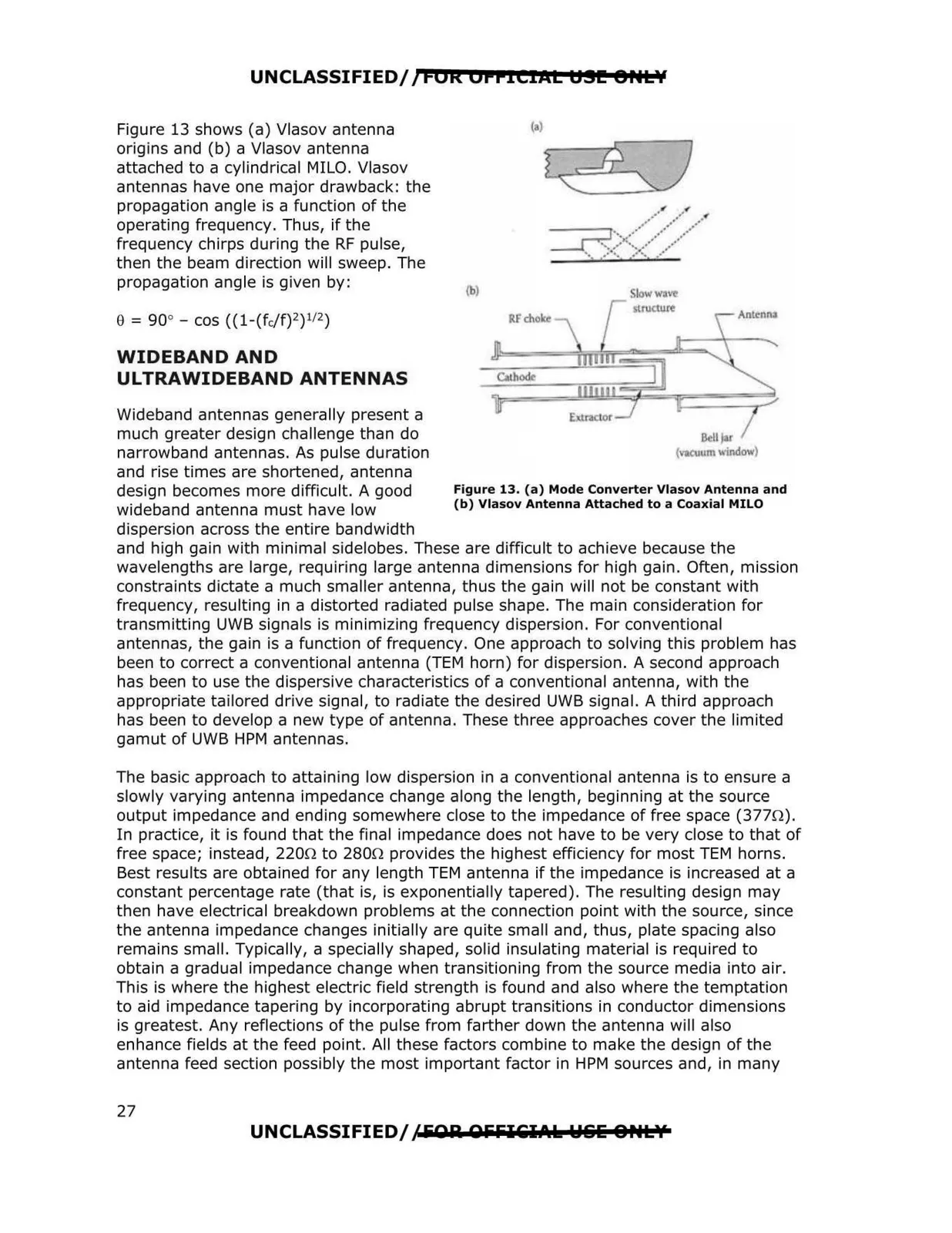
Figure 13 shows (a) Vlasov antenna
origins and (b) a Vlasov antenna
attached to a cylindrical MILO. Vlasov
antennas have one major drawback: the
propagation angle is a function of the
operating frequency. Thus, if the
frequency chirps during the RF pulse,
then the beam direction will sweep. The
propagation angle is given by:
lb)
0 = 90° - cos ((1-(fc/f)2) 112)
WIDEBAND AND
ULTRAWIDEBAND ANTENNAS
Wideband antennas generally present a
much greater design challenge than do
narrowband antennas. As pulse duration
um\\i ndow)
and rise times are shortened, antenna
design becomes more difficult. A good
Figure 13. (a) Mode Converter Vlasov Antenna and
wideband antenna must have low
(b) Vlasov Antenna Attached to a Coaxial MILO
dispersion across the entire bandwidth
and high gain with minimal sidelobes. These are difficult to achieve because the
wavelengths are large, requiring large antenna dimensions for high gain. Often, mission
constraints dictate a much smaller antenna, thus the gain will not be constant with
frequency, resulting in a distorted radiated pulse shape. The main consideration for
transmitting UWB signals is minimizing frequency dispersion . For conventional
antennas, the gain is a function of frequency. One approach to solving this problem has
been to correct a conventional antenna (TEM horn) for dispersion. A second approach
has been to use the dispersive characteristics of a conventional antenna, with the
appropriate tailored drive signal, to radiate the desired UWB signal. A third approach
has been to develop a new type of antenna. These three approaches cover the limited
gamut of UWB HPM antennas.
The basic approach to attaining low dispersion in a conventional antenna is to ensure a
slowly varying antenna impedance change along the length, beginning at the source
output impedance and ending somewhere close to the impedance of free space (377.0).
In practice, it is found that the final impedance does not have to be very close to that of
free space; instead, 220.0 to 280.0 provides the highest efficiency for most TEM horns.
Best results are obtained for any length TEM antenna if the impedance is increased at a
constant percentage rate (that is, is exponentially tapered). The resulting design may
then have electrical breakdown problems at the connection point with the source, since
the antenna impedance changes initially are quite small and, thus, plate spacing also
remains small. Typically, a specially shaped, solid insulating material is required to
obtain a gradual impedance change when transitioning from the source media into air.
This is where the highest electric field strength is found and also where the temptation
to aid impedance tapering by incorporating abrupt transitions in conductor dimensions
is greatest. Any reflections of the pulse from farther down the antenna will also
enhance fields at the feed point. All these factors combine to make the design of the
antenna feed section possibly the most important factor in HPM sources and, in many
UNCLASSIFIED//FOA. OliFICil.\k W&lii 8HL\«
27