AAWSAP DIRD, Inertial Electrostatic Confinement Fusion, March 2010
DOW-UAP-D125 · page 47 of 72
Text
This text came with the file. It may have mistakes. When the text and the image disagree, the image is right.
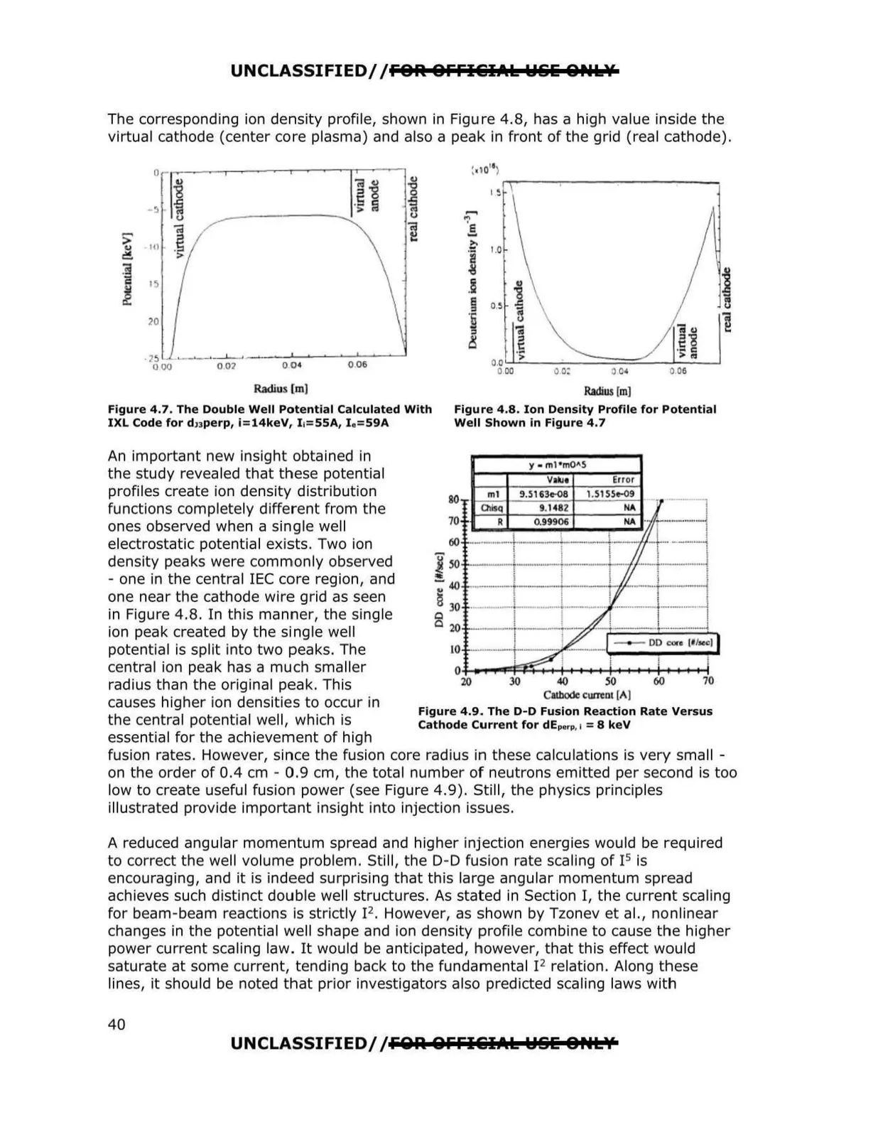
UNCLASSIFIED/ /FOR OFFI&IAk WS& ONkY The corresponding ion density profile, shown in Figure 4.8, has a high value inside the virtual cathode (center core plasma) and also a peak in front of the grid (real cathode). Radius [m) Radius [ml Figure 4.7. The Double Well Potential Calculated With Figure 4.8. Ion Density Profile for Potential IXL Code for d1Jperp, i=14keV, I 1=SSA, I e= S9A Well Shown in Figure 4.7 An important new insight obtained in the study revea led that these potential profiles create ion density distribution functions completely different from the ones observed when a single well electrostatic potential exists. Two ion density peaks were commonly observed - one in the central IEC core region, and one near the cathode wire grid as seen in Figure 4.8. In this manner, the single ion peak created by the single well potential is split into two peaks. The central ion peak has a much sma ller radius than the original peak. This causes higher ion densities to occur in 20 30 40 so Cllhodc CWTCDI [Al 60 70 Figure 4.9. The D-D Fusion Reaction Rate Versus the central potential well, which is Cathode Current for dEperp, 1 =8 keV essential for the achievement of high fusion rates. However, since the fusion core radius iin these calculations is very sma ll on the order of 0.4 cm - 0.9 cm, the total number of neutrons emitted per second is too low to create useful fusion power (see Figure 4.9). Still, the physics principles Illustrated provide important insight into injection issues. A reduced angular momentum spread and higher injection energies would be required to correct the well volume problem. Still, the 0-0 fusion rate scaling of 15 is encouraging, and it is indeed surprising that this large angular momentum spread achieves such distinct double well structures. As stated in Section I, the current scaling for beam -beam reactions is strictly 12. However, as shown by Tzonev et al., nonlinear changes in the potential well shape and ion density profile combine to cause the higher power current scaling law. It would be anticipated, however, that this effect would saturate at some current, tending back to the fundamental I2 relation. Along these lines, it should be noted that prior investigators also predicted scaling laws with y - ml•mOAS Error 80 ml 9.5163c-08 1.51 SSe-09 Ot q 9. 1482 NA 70 R 0.99906 60 j 50+----+-----+--+--•/'f' - - 40 _ ________, ~ 30 0 o wr--;r---,--zr--;t:====t===:::1...,. o.i...-,.:j~.:+-t-1-+-+++-+-+-+-t~~......+-1 UNCLASSIFIED/ /FOA &FFI&IAk WSE O,.LY 40