AAWSAP DIRD, Inertial Electrostatic Confinement Fusion, March 2010
DOW-UAP-D125 · page 5 of 72
Text
This text came with the file. It may have mistakes. When the text and the image disagree, the image is right.
UNCLASSIFIED/,SFOA OFFI&IAk WSE 8Ptklf
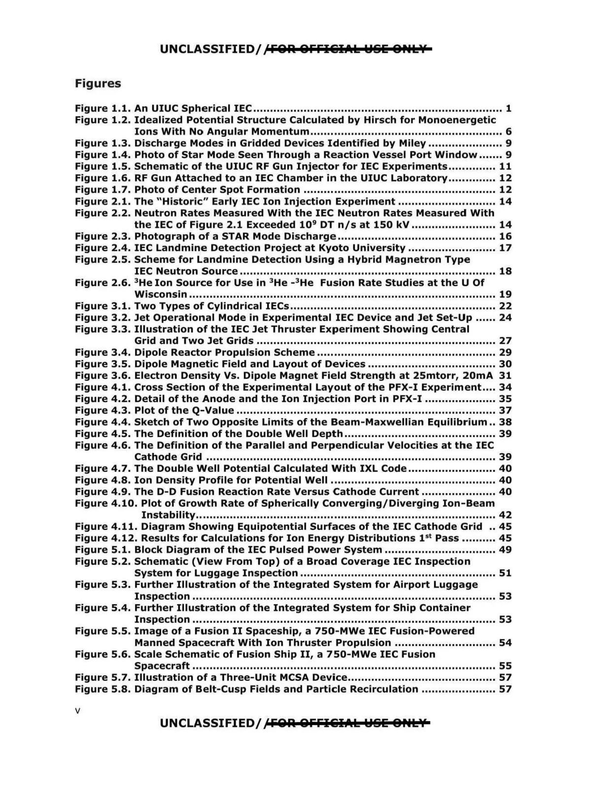
Figures
Figure 1.1. An UIUC Spherical IEC .............................................................................. 1
Figure 1.2. Idealized Potential Structure Calculated by Hirsch for Monoenergetic
Figure 2.2. Neutron Rates Measured With the IEC: Neutron Rates Measured With
Figure 2.5. Scheme for Landmine Detection Using a Hybrid Magnetron Type
Figure 2.6. 3He Ion Source for Use in 3He - 3He Fusion Rate Studies at the U Of
Figure 3.3. Illustration of the IEC Jet Thruster Experiment Showing Central
Figure 4.6. The Definition of the Parallel and Perpendicular Velocities at the IEC
Figure 4.10. Plot of Growth Rate of Spherically Converging/Diverging Ion-Beam
Ions With No Angular Momentum ......................................................... 6
Figure 1.3. Discharge Modes in Gridded Devices Identified by Miley ...................... 9
Figure 1.4. Photo of Star Mode Seen Through a Reaction Vessel Port Window ....... 9
Figure 1.5. Schematic of the UIUC RF Gun Injector for IEC Experiments .............. 11
Figure 1.6. RF Gun Attached to an IEC Chamber in the UIUC Laboratory.............. 12
Figure 1.7. Photo of Center Spot Formation ......................................................... 12
Figure 2.1. The "Historic" Early IEC Ion Injection Experiment ............................. 14
the IEC of Figure 2.1 Exceeded 109 DT n/s at 150 kV ......................... 14
Figure 2.3. Photograph of a STAR Mode Discharge ............................................... 16
Figure 2.4. IEC Landmine Detection Project at Kyoto University .......................... 17
IEC Neutron Source ............................................................................ 18
Wisconsin ............................................................................................ 19
Figure 3.1. Two Types of Cylindrical IECs ............................................................. 22
Figure 3.2. Jet Operational Mode in Experimental IEC Device and Jet Set-Up ...... 24
Grid and Two Jet Grids ....................................................................... 27
Figure 3.4. Dipole Reactor Propulsion Scheme ..................................................... 29
Figure 3.5. Dipole Magnetic Field and Layout of Devices ...................................... 30
Figure 3.6. Electron Density Vs. Dipole Magnet Field Strength at 25mtorr, 20mA 31
Figure 4.1. Cross Section of the Experimental Layout of the PFX-I Experiment.... 34
Figure 4.2. Detail of the Anode and the Ion Injection Port in PFX-I ..................... 35
Figure 4.3. Plot of the Q-Value ............................................................................. 37
Figure 4.4. Sketch of Two Opposite Limits of the Beam-Maxwellian Equilibrium .. 38
Figure 4.5. The Definition of the Double Well Depth ............................................. 39
Cathode Grid ...................................................................................... 39
Figure 4.7. The Double Well Potential Calculated With IXL Code ......................... 40
Figure 4.8. Ion Density Profile for Potential Well ................................................. 40
Figure 4.9. The D-D Fusion Reaction Rate Versus Cathode Current ..................... 40
Instability......................................................................................... 42
Figure 4.11. Diagram Showing Equipotential Surfaces of the IEC Cathode Grid .. 45
Figure 4.12. Results for Calculations for Ion Energy Distributions 1st Pass ......... 45
Figure 5.1. Block Diagram of the IEC Pulsed Power System ................................. 49
Figure 5.2. Schematic (View From Top) of a Broad Coverage IEC Inspection
System for Luggage Inspection ··············································••11••······· 51
Figure 5.3. Further Illustration of the Integrated System for Airport Luggage
Inspection ........................................................................................... 53
Figure 5.4. Further Illustration of the Integrated .System for Ship Container
Inspection .......................................................................................... 53
Figure S.S. Image of a Fusion II Spaceship, a 750-MWe IEC Fusion-Powered
Manned Spacecraft With Ion Thruster Propulsion ............................. 54
Figure 5.6. Scale Schematic of Fusion Ship II, a 750-MWe IEC Fusion
Spacecraft .......................................................................................... 55
Figure 5.7. Illustration of a Three-Unit MCSA Device............................................ 57
Figure 5.8. Diagram of Belt-Cusp Fields and Particle Recirculation ............ ........... 57
UNCLASSIFIED/ ,CFOA OFFI&IAk WSE 8PtLY
V