AAWSAP DIRD, MHD Air Breathing Propulsion and Power for Aerospace Applications, November 2010
DOW-UAP-D149 · page 12 of 32
Text
This text came with the file. It may have mistakes. When the text and the image disagree, the image is right.
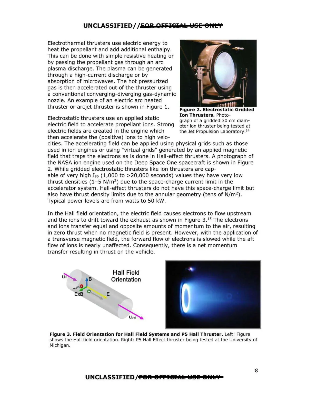
UNCLASSIFIED//FOR 055iliCl.t.k WSE 8HL'f Electrothermal thrusters use electric energy to heat the propellant and add additional enthalpy. This can be done with simple resistive heating or by passing the propellant gas through an arc plasma discharge. The plasma can be generated through a high-current discharge or by absorption of microwaves. The hot pressurized gas is then accelerated out of the thruster using a conventional converging-diverging gas-dynamic nozzle. An example of an electric arc heated thruster or arcjet thruster is shown in Figure 1. Electrostatic thrusters use an applied static electric field to accelerate propellant ions. Strong electric fields are created in the engine which then accelerate the (positive) ions to high velo cities. The accelerating field can be applied using physical grids such as those used in ion engines or using "virtual grids" generated by an applied magnetic field that traps the electrons as is done in Hall-effect thrusters. A photograph of the NASA ion engine used on the Deep Space One spacecrah is shown in Figure 2. While gridded electrostatic thrusters like ion thrusters are cap able of very high l sp (1,000 to >20,000 seconds) values they have very low thrust densities (1-5 N/m2) due to the space-charge current limit in the accelerator system. Hall-effect thrusters do not have this space-charge limit but also have thrust density limits due to the annular geometry (tens of N/m2). Typical power levels are from watts to 50 kW. In the Hall field orientation, the electric field causes electrons to flow upstream and the ions to drih toward the exhaust as shown in Figure 3. 15 The electrons and ions transfer equal and opposite amounts of momentum to the air, resulting in zero thrust when no magnetic field is present. However, with the application of a transverse magnetic field, the forward flow of electrons is slowed while the ah flow of ions is nearly unaffected. Consequently, there is a net momentum transfer resulting in thrust on the vehicle. Figure 2. Electrostatic Gridded Ion Thrusters. Photo- graph of a gridded 30 cm diam eter ion thruster being tested at the Jet Propulsion Laboratory .14 E Hall Field Orientation Figure 3. Field Orientation for Hall Field Systems and PS Hall Thruster. Left: Figure shows the Hall field orientation. Right: PS Hall Effect thruster being tested at the University of Michigan. UNCLASSIFIEDff8fl 8ffl@IIIIL ~BE 8HLY 8