AAWSAP DIRD, Quantum Computing and Utilizing Organic Molecules in Automation Technology, December 2010
DOW-UAP-D150 · page 4 of 54
Text
This text came with the file. It may have mistakes. When the text and the image disagree, the image is right.
UNCLASSIFIED//P91t 9PPl@IAL l:ISIE 8HLY
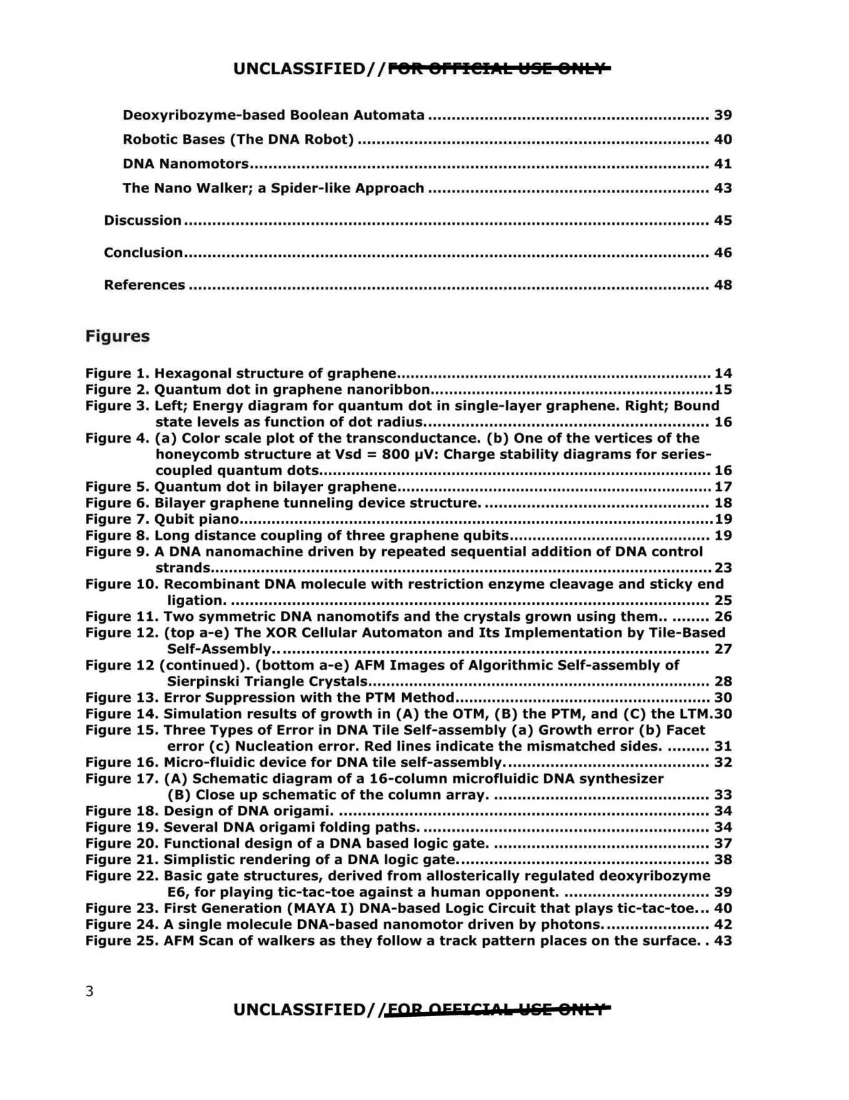
Deoxyribozyme-based Boolean Automata ............................................................ 39
Robotic Bases (The DNA Robot) ........................................................................... 40
DNA Nanomotors.................................................................................................. 41
The Nano Walker; a Spider-like Approach ............................................................ 43
Discussion ................................................................................................................ 45
Conclusion................................................................................................................ 46
References ................................................................................................................ 48
Figures
Figure 1. Hexagonal structure of graphene..................................................................... 14
Figure 2. Quantum dot in graphene nanoribbon..............................................................15
Figure 3. Left; Energy diagram for quantum dot in single-layer graphene. Right; Bound
state levels as function of dot radius............................................................. 16
Figure 4. (a) Color scale plot of the transconductance. (b) One of the vertices of the
honeycomb structure at Vsd = 800 µV: Charge stability diagrams for series-
coupled quantum dots...................................................................................... 16
Figure 5. Quantum dot in bilayer graphene..................................................................... 17
Figure 6. Bilayer graphene tunneling device structure................................................. 18
Figure 7. Qubit piano........................................................................................................19
Figure 8. Long distance coupling of three graphene qubits............................................ 19
Figure 9. A DNA nanomachine driven by repeated sequential addition of DNA control
strands..............................................................................................................23
Figure 10. Recombinant DNA molecule with restriction enzyme cleavage and sticky end
ligation....................................................................................................... 25
Figure 11. Two symmetric DNA nanomotifs and the crystals grown using them.......... 26
Figure 12. (top a-e) The XOR Cellular Automaton and Its Implementation by Tile-Based
Self-Assembly............................................................................................. 27
Figure 12 (continued). (bottom a-e) AFM Images of Algorithmic Self-assembly of
Sierpinski Triangle Crystals........................................................................... 28
Figure 14. Simulation results of growth in (A} the OTM, (B) the PTM, and (C} the LTM.30
Figure 15. Three Types of Error in DNA Tile Self-assembly (a) Growth error (b) Facet
Figure 13. Error Suppression with the PTM Method........................................................ 30
error (c) Nucleation error. Red lines indicate the mismatched sides.......... 31
Figure 16. Micro-fluidic device for DNA tile self-assembly............................................ 32
Figure 17. (A) Schematic diagram of a 16-column microfluidic DNA synthesizer
(B) Close up schematic of the column array............................................... 33
Figure 18. Design of DNA origami................................................................................ 34
Figure 19. Several DNA origami folding paths.............................................................. 34
Figure 20. Functional design of a DNA based logic gate............................................... 37
Figure 21. Simplistic rendering of a DNA logic gate...................................................... 38
Figure 22. Basic gate structures, derived from allosterically regulated deoxyribozyme
E6, for playing tic-tac-toe against a human opponent................................ 39
Figure 23. First Generation (MAYA I) DNA-based Logic Circuit that plays tic-tac-toe... 40
Figure 24. A single molecule DNA-based nanomotor driven by photons....................... 42
Figure 25. AFM Scan of walkers as they follow a track pattern places on the surface.. 43
UNCLASSIFIED//EAR OEEICI Pk Wlili BHLY
3