Department of the Air Force Report, 1996
DOW-UAP-D048 · page 17 of 181
Text
This text came with the file. It may have mistakes. When the text and the image disagree, the image is right.
however, involve the quantity R which is expressed explicitly as a function of R and only
implicitly as a function·of time. Values of R from the nominal trajectory are differenced to
computeR.
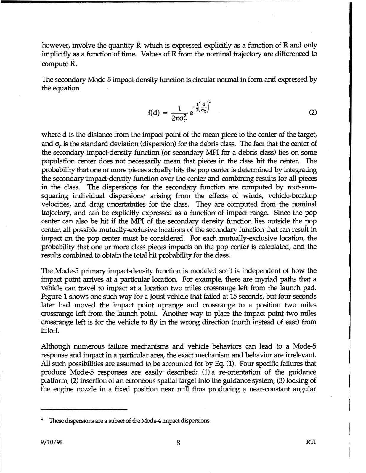
The secondary Mode-5 impact-density function is circular normal in form and expressed by
the equation
(2)
where d is the distance from the impact point of the mean piece to the center of the target,
and oc is the standard deviation (dispersion) for the debris class. The fact that the center of
the secondary impact-density function (or secondary MPI for a debris class) lies Off some
population center does not necessarily mean that pieces in the class hit the center. The
probability that one or more pieces actually hits the pop center is determined by integrating
the secondaryimpact-density function over the center and combining results for all pieces
in the class. The dispersions for the secondary function are computed by root-sum-
squaring individual dispersions• arising from the effects of winds, vehicle-breakup
velocities, and drag uncertainties for the class. They are computed from the nominal
trajectory, and cari be explicitly expressed as a function· of impact range. Since the pop
center can also be hit if the MPI of the secondary density function lies outside the pop
center, all possible mutually-exclusive locations of the secondary function that can result in
impact on the pop center must be considered. For each mutually-exclusive location, the
probability that one or more class pieces impacts on the pop center is calculated, and the
results combined to obtain the total hit probability for the class.
The Mode-5 primary impact-density function is modeled so· it is independent of how the
impact point arrives at a particular location For example, there are myriad paths that a
vehicle can travel to impact at a location two miles crossrange left from the launch pad.
Figure 1 shows one such way for a Joust vehicle that failed at 15 seconds, but four seconds
later had moved the impact point uprange and CTO$!ange to a position two miles
crossrange left from the launch point. Another way to place the impact point two- miles
•crossrange left is for the vehicle to fly in the wrong direction (north instead of east) from
liftoff.
Although numerous failure mechanisms and vehicle behaviors can lead to a Mode-5
response and impact in a particular area, the exact mechanism and behavior are irrelevant
All such possibilities are assumed to be accounted for by Eq. (1). Four specific failures that
produce Mode-5 responses are easily- described: (1) a re-orientation of the guidance
platform, (2) insertion of an erroneous spatial target into the guidance system, (3) locking of
the engine nozzle in a fixed position near null thus producing a near-constant angular
* These dispersions are a subset of the Mode-4 impact dispersions.
9/10/96
8
RTI