AAWSAP DIRD, Pulsed High-Power Microwave Source Technology, January 2010
DOW-UAP-D121 · page 20 of 37
Text
This text came with the file. It may have mistakes. When the text and the image disagree, the image is right.
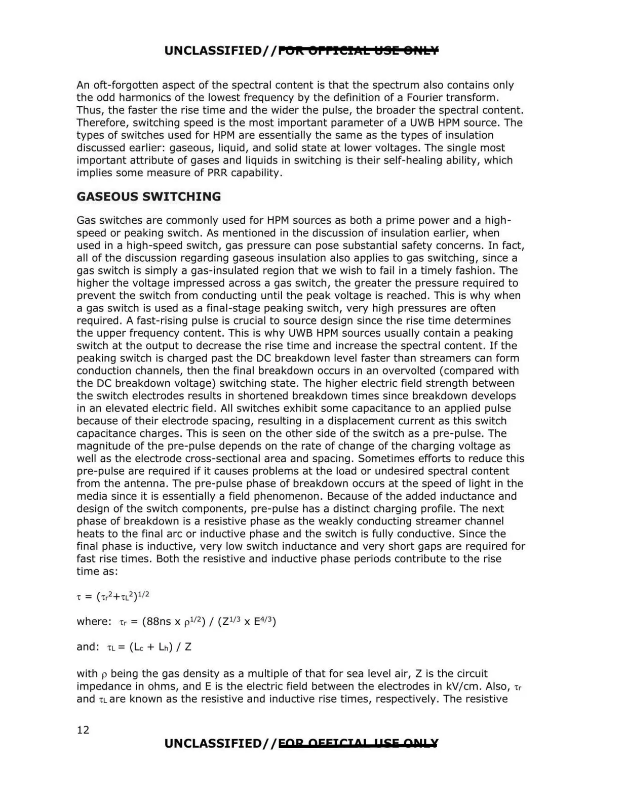
UNCLASSIFIED//POI\ OPPICIJllt l!l!H! e ..tv An oft-forgotten aspect of the spectral content is that the spectrum also contains only the odd harmonics of the lowest frequency by the definition of a Fourier transform . Thus, the faster the rise time and the wider the pulse, the broader the spectral content. Therefore, switching speed is the most important parameter of a UWB HPM source. The types of switches used for HPM are essentially the same as the types of insulation discussed earlier: gaseous, liquid, and solid state at lower voltages. The single most important attribute of gases and liquids in switching is their self-healing ability, which implies some measure of PRR capability. GASEOUS SWITCHING Gas switches are commonly used for HPM sources as both a prime power and a high speed or peaking switch. As mentioned in the discussion of insulation earlier, when used in a high-speed switch, gas pressure can pose substantial safety concerns. In fact, all of the discussion regarding gaseous insulation also applies to gas switching, since a gas switch is simply a gas-insulated region that we wish to fail in a timely fashion. The higher the voltage impressed across a gas switch, the greater the pressure required to prevent the switch from conducting until the peak voltage is reached. This is why when a gas switch is used as a final-stage peaking switch, very high pressures are often required. A fast-rising pulse is crucial to source design since the rise time determines the upper frequency content. This is why UWB HPM sources usually contain a peaking switch at the output to decrease the rise time and increase the spectral content. If the peaking switch is charged past the DC breakdown level faster than streamers can form conduction channels, then the final breakdown occurs in an overvolted (compared with the DC breakdown voltage) switching state. The higher electric field strength between the switch electrodes results in shortened breakdown times since breakdown develops in an elevated electric field. All switches exhibit some capacitance to an applied pulse because of their electrode spacing, resulting in a displacement current as this switch capacitance charges. This is seen on the other side of the switch as a pre-pulse. The magnitude of the pre-pulse depends on the rate of change of the charging voltage as well as the electrode cross-sectional area and spacing. Sometimes efforts to reduce this pre-pulse are required if it causes problems at the load or undesired spectral content from the antenna. The pre-pulse phase of breakdown occurs at the speed of light in the media since it is essentially a field phenomenon. Because of the added inductance and design of the switch components, pre-pulse has a distinct charging profile. The next phase of breakdown is a resistive phase as the weakly conducting streamer channel heats to the final arc or inductive phase and the switch is fully conductive. Since the final phase is inductive, very low switch inductance and very short gaps are required for fast rise times. Both the resistive and inductive phase periods contribute to the rise time as: 2 1 3 4 3 where: -rr = (88ns x p 1 f (Z 1 x E 1 ) / ) with p being the gas density as a multiple of that for sea level air, Z is the circuit impedance in ohms, and E is the electric field between the electrodes in kV/cm. Also, ,r and TL are known as the resistive and inductive rise times, respectively. The resistive UNCLASSIFIED//FOR OFFICIO! 1 !SE ON! Y 12