AAWSAP DIRD, Pulsed High-Power Microwave Source Technology, January 2010
DOW-UAP-D121 · page 29 of 37
Text
This text came with the file. It may have mistakes. When the text and the image disagree, the image is right.
UNCLASSIFIED//FOlt err1e1J1ct YSI!! e ..tv
uses a pulse transformer to charge a short section of coaxial transmission line to high
voltage. The transmission line is charged quickly enough to overvolt a high -pressure
(2,000-psi) hydrogen switch, providing 120-ps rise-time pulses at about 350 kV and
2.5-ns pulse width to another 40Q coaxial transmission line, which uses a point
geometry converter (PGC) to feed an antenna .
Figure 5 shows H2 with a PGC output
driving a large TEM horn. The peak
power is 2 GW, and these sources were
capable of a power supply-limited PRR
of 1.8 kHz. Using a flat-plate TEM horn
antenna, the radiated field at 10 meters
was 25 kV/m. At the AFRL, they
compare HPM sources using what is
termed a figure of merit (FOM), defined
as the field value at some distance
multiplied by the distance. Thus, for H3
the FOM is 250 kV. While developing the
H series of HPM sources, scientists
Figure 5. H2 With Large TEM Horn and PGC Output
devised a means of efficiently
converting from a coaxial geometry to a parallel-plate geometry. Radiation from a coax
forms a doughnut pattern with no field on bore site, and thus the PGC was developed to
feed a more interesting antenna.
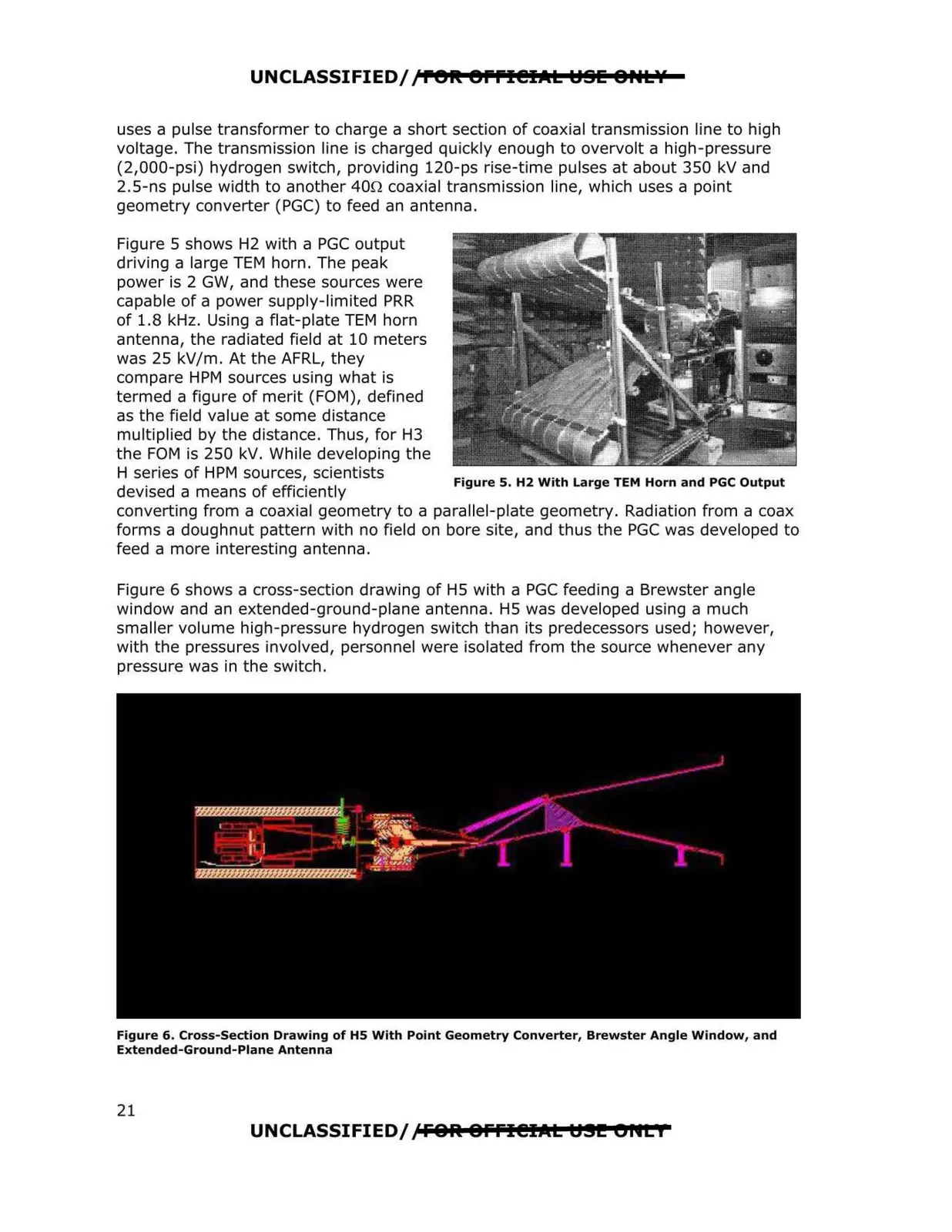
Figure 6 shows a cross-section drawing of HS with a PGC feeding a Brewster angle
window and an extended-ground-plane antenna. HS was developed using a much
smaller volume high-pressure hydrogen switch than its predecessors used; however,
with the pressures involved, personnel were isolated from the source whenever any
pressure was in the switch.
Figure 6. Cross-Section Drawing of HS With Point Geometry Converter, Brewster Angle Window, and
Extended-Ground-Plane Antenna
UNCLASSIFIED/fFOlit 8ffl@IAL U.!!! l>HL I
21