AAWSAP DIRD, Invisibility Cloaking Theory and Experiments, March 2010
DOW-UAP-D122 · page 17 of 29
Text
This text came with the file. It may have mistakes. When the text and the image disagree, the image is right.
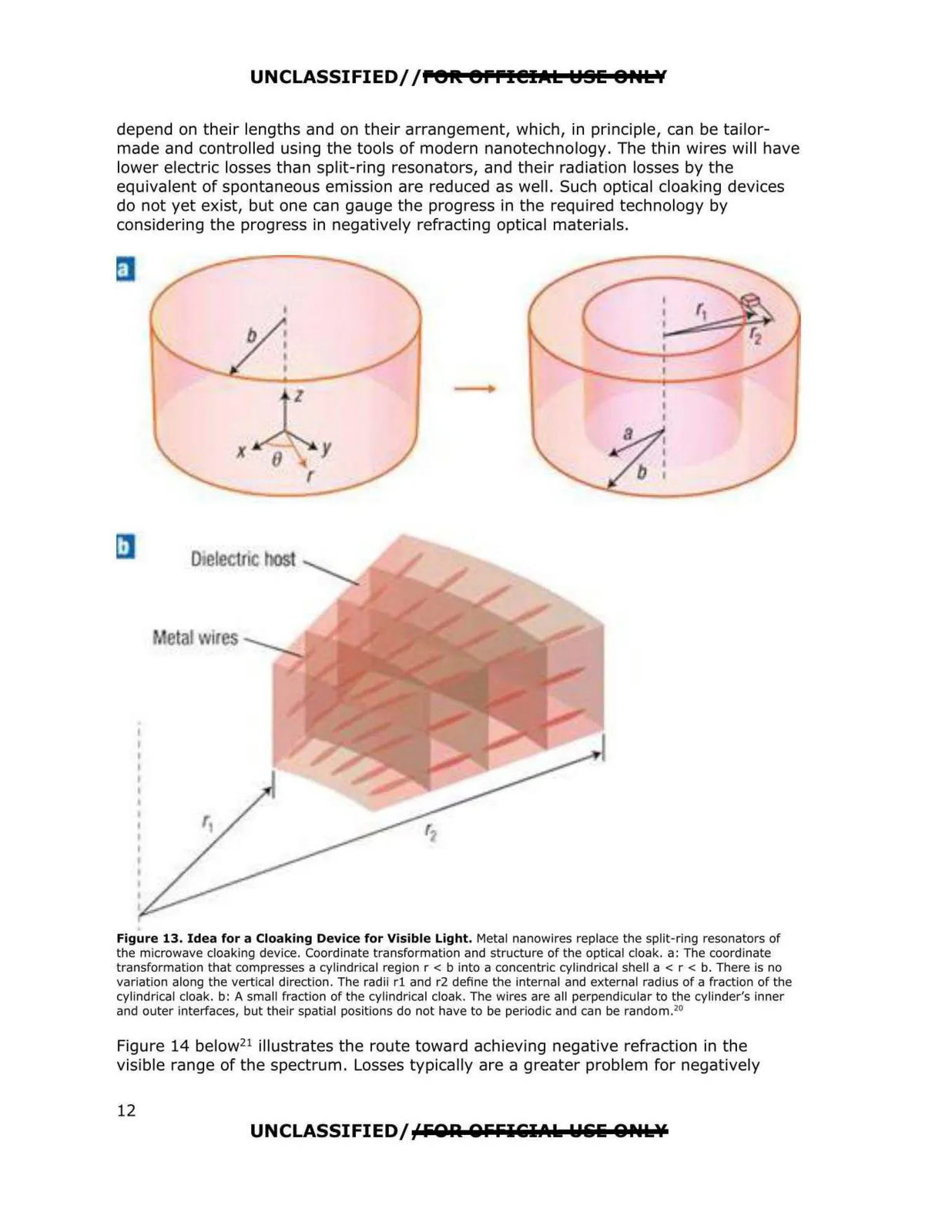
UNCLASSIFIED/ /POR: errl@IAL YSI: 8HLY depend on t heir lengt hs and on their arrangement, which, in principle, can be tailor made and controlled using the tools of modern nanotechnology. The thin wires will have lower electric losses than split-ring resonators, and their radiation losses by the equivalent of spontaneous emission are reduced as well. Such optical cloaking devices do not yet exist, but one can gauge the progress in the required technology by considering the progress in negatively refracti ng optical materials. Figure 13. Idea for a Cloaking Device for Visible Light. Metal nanowires replace the split-ring resonators of the microwave cloaking device. Coordinate transformation and structure of the optical cloak. a: The coordinate transformation that compresses a cylindrical region r < b into a concentric cylindrical shell a < r < b. There is no variation along the vertical direction. The radii rl and r2 define the internal and external radius of a fraction of the cylindrical cloak . b: A small fraction of the cylindrical cloak. The wires are all perpendicular to the cylinder's inner and outer interfaces, but their spatial positions do not have to be periodic and can be random.20 Figure 14 below21 illustrates the route toward achieving negative refraction in the visible range of the spectrum. Losses typically are a greater problem for negatively UNCLASSIFIEDJ;<fOA OFFitI.t.k Wlili QPUsY 12