AAWSAP DIRD, Space Access: Where We’ve Been and Where We Could Go, March 2010
DOW-UAP-D124 · page 15 of 56
Text
This text came with the file. It may have mistakes. When the text and the image disagree, the image is right.
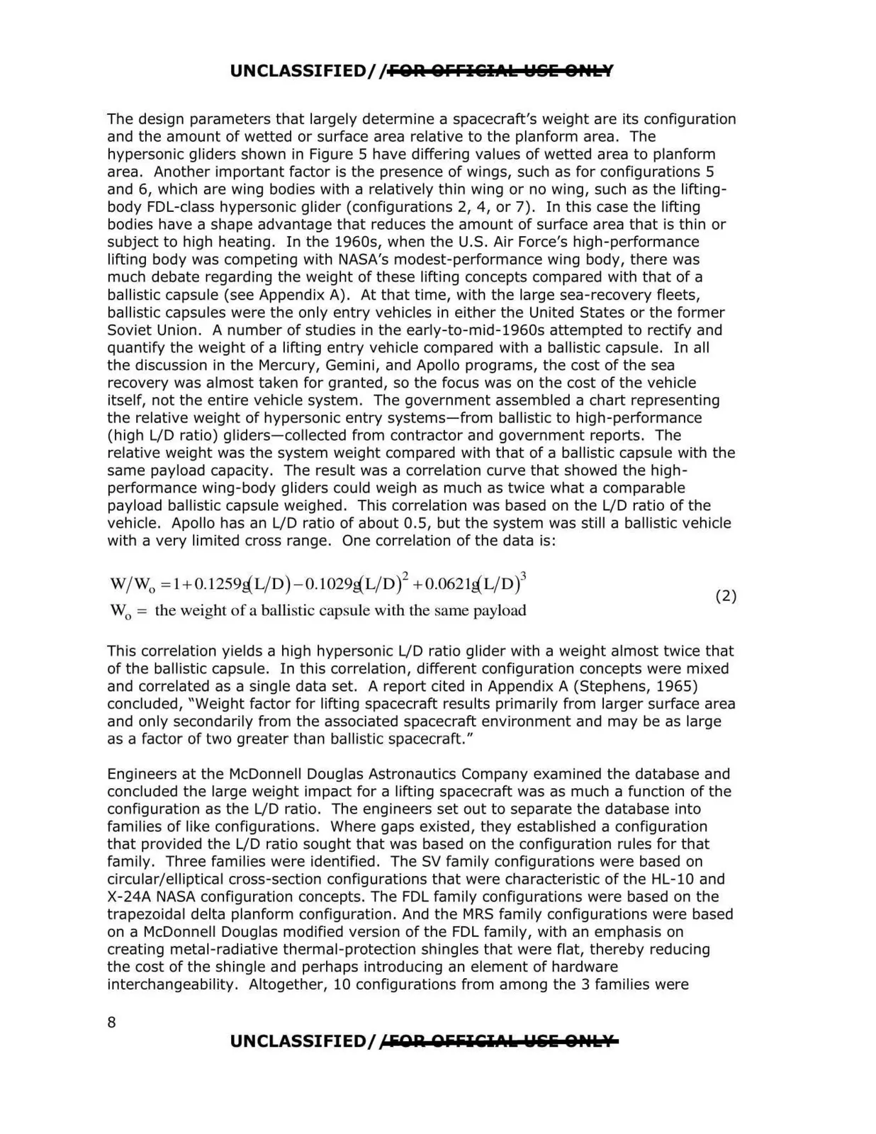
UNCLASSIFIED//FOR OFFl&IAl l:ISlii 8,.lY The design parameters that largely determine a spacecraft's weight are its configuration and the amount of wetted or surface area relative to the planform area. The hypersonic gliders shown in Figure 5 have differing values of wetted area to planform area. Another important factor is the presence of wings, such as for configurations 5 and 6, which are wing bodies with a relatively thin wing or no wing, such as the lifting body FDL-class hypersonic glider (configurations 2, 4, or 7). In this case the lifting bodies have a shape advantage that reduces the amount of surface area that is thin or subject to high heating. In the 1960s, when the U.S. Air Force's high-performance lifting body was competing with NASA's modest-performance wing body, there was much debate regarding the weight of these lifting concepts compared with that of a ballistic capsule (see Appendix A). At that time, with the large sea-recovery fleets, ballistic capsules were the only entry vehicles in either the United States or the former Soviet Union. A number of studies in the early-to-mid-1960s attempted to rectify and quantify the weight of a lifting entry vehicle compared with a ballistic capsule. In all the discussion in the Mercury, Gemini, and Apollo programs, the cost of the sea recovery was almost taken for granted, so the focus was on the cost of the vehicle itself, not the entire vehicle system. The government assembled a chart representing the relative weight of hypersonic entry systems-from ballistic to high-performance (high L/D ratio) gliders-collected from contractor and government reports. The relative weight was the system weight compared with that of a ballistic capsule with the same payload capacity. The result was a correlation curve that showed the high performance wing-body gliders could weigh as much as twice what a comparable payload ballistic capsule weighed. This correlation was based on the L/D ratio of the vehicle. Apollo has an L/D ratio of about 0.5, but the system was still a ballistic vehicle with a very limited cross range. One correlation of the data is: W/W0 =l + 0.1259aL/D)-0.1029aL/D)2 + 0.0621aL/D)3 (2) W = the weight of a ballistjc capsule with the same payload 0 This correlation yields a high hypersonic L/D ratio glider with a weight almost twice that of the ballistic capsule. In this correlation, different configuration concepts were mixed and correlated as a single data set. A report cited in Appendix A (Stephens, 1965) concluded, "Weight factor for lifting spacecraft results primarily from larger surface area and only secondarily from the associated spacecraft environment and may be as large as a factor of two greater than ballistic spacecraft." Engineers at the McDonnell Douglas Astronautics Company examined the database and concluded the large weight impact for a lifting spacecraft was as much a function of the configuration as the L/D ratio. The engineers set out to separate the database into families of like configurations. Where gaps existed, they established a configuration that provided the L/D ratio sought that was based on the configuration rules for that family. Three fam ilies were identified. The SV family configurations were based on circular/elliptical cross-section configurations that were characteristic of the HL-10 and X-24A NASA configuration concepts. The FDL family configurations were based on the trapezoidal delta planform configuration. And the MRS family configurations were based on a McDonnell Douglas modified version of the FDL family, with an emphasis on creating metal-radiative thermal-protection shingles that were flat, thereby reducing the cost of the shingle and perhaps introducing an element of hardware interchangeability. Altogether, 10 configurations from among the 3 families were 8 UNCLASSIFIED//FOR OFFICilAk Wliliii OPtllf