AAWSAP DIRD, Space Access: Where We’ve Been and Where We Could Go, March 2010
DOW-UAP-D124 · page 14 of 56
Text
This text came with the file. It may have mistakes. When the text and the image disagree, the image is right.
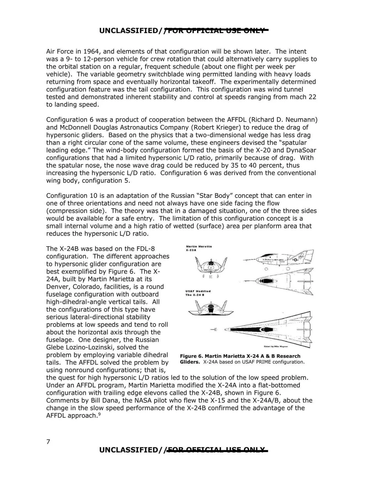
UNCLASSIFIED/; FOR OFFICIAL U.!I! er~t'f Air Force in 1964, and elements of that configuration will be shown later. The intent was a 9- to 12-person vehicle for crew rotation that could alternatively carry supplies to the orbital station on a regular, frequent schedule (about one flight per week per vehicle) . The variable geometry switchblade wing permitted landing with heavy loads returning from space and eventually horizontal takeoff. The experimentally determined configuration feature was the tail configuration. This configuration was wind tunnel tested and demonstrated inherent stability and control at speeds ranging from mach 22 to landing speed. Configuration 6 was a product of cooperation between the AFFDL (Richard D. Neumann) and McDonnell Douglas Astronautics Company (Robert Krieger) to reduce the drag of hypersonic gliders. Based on the physics that a two-dimensional wedge has less drag than a right circular cone of the same volume, these engineers devised the "spatular leading edge." The wind-body configuration formed the basis of the X-20 and DynaSoar configurations that had a limited hypersonic L/D ratio, primarily because of drag. With the spatular nose, the nose wave drag could be reduced by 35 to 40 percent, thus increasing the hypersonic L/D ratio. Configuration 6 was derived from the conventional wing body, configuration 5. Configuration 10 is an adaptation of the Russian "Star Body" concept that can enter in one of three orientations and need not always have one side facing the flow (compression side). The theory was that in a damaged situation, one of the three sides would be available for a safe entry. The limitation of this configuration concept is a small internal volume and a high ratio of wetted (surface) area per planform area that reduces the hypersonic L/D ratio. The X-24B was based on the FDL-8 Martin Mar•tt ■ X-23A configuration. The different approaches to hypersonic glider configuration are best exemplified by Figure 6. The X 24A, built by Martin Marietta at its Denver, Colorado, facilities, is a round fuselage configuration with outboard high-dihedral-angle vertical tails. All the configurations of this type have serious lateral-directional stability problems at low speeds and tend to roll about the horizontal axis through the fuselage . One designer, the Russian Glebe Lozino-Lozinski, solved the problem by employing variable dihedral Figure 6. Martin Marietta X-24 A& BResearch tails. The AFFDL solved the problem by Gliders. X-24A based on USAF PRIME configuration. using nonround configurations; that is, the quest for high hypersonic L/D ratios led to the solution of the low speed problem. Under an AFFDL program, Martin Marietta modified the X-24A into a flat-bottomed configuration with trailing edge elevens called the X-24B, shown in Figure 6. Comments by Bill Dana, the NASA pilot who flew the X-15 and the X-24A/B, about the change in the slow speed performance of the X-24B confirmed the advantage of the AFFDL approach.9 l' 0[ USA f Mod1lied Th• X·24 I UNCLASSIFIED//EAR AEEJCJOP 1155 All! X 7