AAWSAP DIRD, Space Access: Where We’ve Been and Where We Could Go, March 2010
DOW-UAP-D124 · page 37 of 56
Text
This text came with the file. It may have mistakes. When the text and the image disagree, the image is right.
UNCLASSIFIED/f FOlil OFFIEJIAL l:181: 8HLY
Up-and-Down Operations
For an aircraft, the takeoff mode is not an issue: it is a runway takeoff and runway
landing. However, for a space launcher, the issue is not so clear-cut. With mass ratios
for launchers much greater than for aircraft ( 4 to 8, compared with less than 2 for
aircraft), runway speed is impractical for some launchers with high mass ratios. The
principal option is vertical takeoff, with horizontal landing remaining viable. The
problem is that in some launcher studies, the study directives mandated horizontal
takeoff regardless of the mass ratio. Many launcher studies have been thwarted by this
a priori dictate of horizontal takeoff. Air-breathing propulsion is then stuck with a "too
heavy" label because of the dictated takeoff mode. In reality, horizontal or vertical
takeoff, like the configuration concept, is less a choice than a result of the propulsion
concept selected. Horizontal takeoff requires that the wing loading be compatible with
the lift coefficient the configuration can generate and the maximum takeoff speed limit.
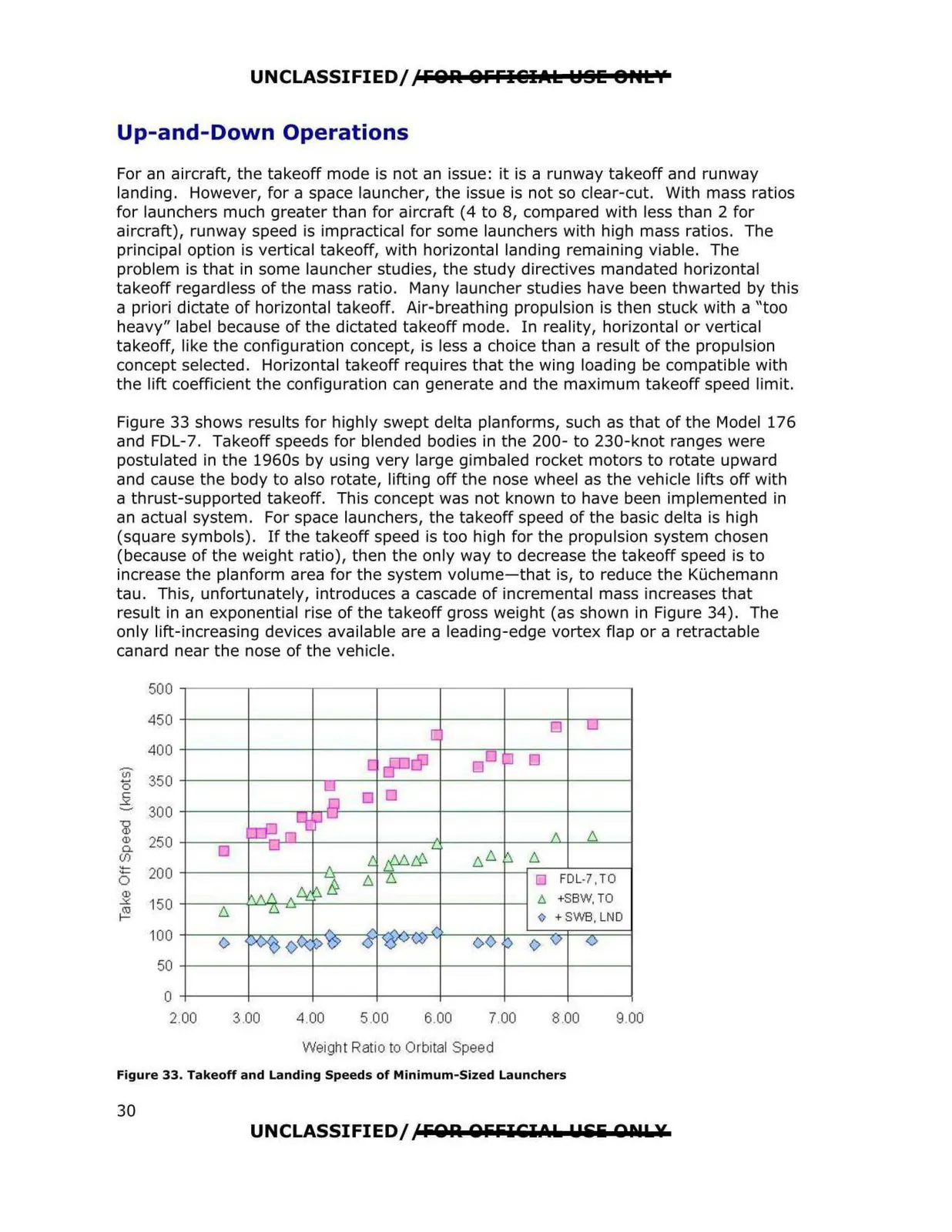
Figure 33 shows results for highly swept delta planforms, such as that of the Model 176
and FDL-7. Takeoff speeds for blended bodies in the 200- to 230-knot ranges were
postulated in the 1960s by using very large gimbaled rocket motors to rotate upward
and cause the body to also rotate, lifting off the nose wheel as the vehicle lifts off with
a thrust-supported takeoff. This concept was not known to have been implemented in
an actual system. For space launchers, the takeoff speed of the basic delta is high
(square symbols). If the takeoff speed is too high for the propulsion system chosen
(because of the weight ratio), then the only way to decrease the takeoff speed is to
increase the planform area for the system volume-that is, to reduce the KUchemann
tau. This, unfortunately, introduces a cascade of incremental mass increases that
result in an exponential rise of the takeoff gross weight (as shown in Figure 34). The
only lift-increasing devices available are a leading-edge vortex flap or a retractable
canard near the nose of the vehicle.
500
450
400
U)
0
350
_§
300
'D
Q)
Q)
Cl.
250
(/)
:J=
0
200
Q)
.:,,:,
150
~
100
50
0
2.00
3.00
4.00
5.00
6.00
7.00
8.00
9.00
Weight Ratio to Orbital Spee d
Figure 33. Takeoff and Landing Speeds of Minimum-Sized Launchers
UNCLASSIFIED/ ,C FOA OlililCI CL: Pili ODIL:¥
I:,.
◊
0
0
□ FDL-7,TO
30