AAWSAP DIRD, Space Access: Where We’ve Been and Where We Could Go, March 2010
DOW-UAP-D124 · page 4 of 56
Text
This text came with the file. It may have mistakes. When the text and the image disagree, the image is right.
UNCLASSIFIED/ /POI': OPPIEIJct t:191! BHL'f
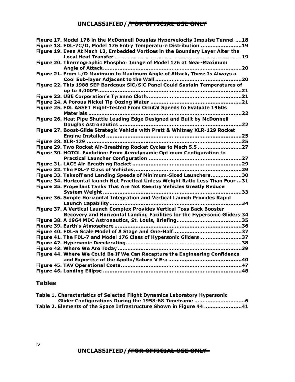
Figure 17. Model 176 in the McDonnell Douglas Hypervelocity Impulse Tunnel ....18
Figure 18. FDL-7C/D, Model 176 Entry Temperature Distribution .........................19
Figure 19. Even At Mach 12, Embedded Vortices in the Boundary Layer Alter the
Local Heat Transfer ..............................................................................19
Figure 20. Thermographic Phosphor Image of Model 176 at Near-Maximum
Angle of Attack .....................................................................................20
Figure 21. From L/D Maximum to Maximum Angle of Attack, There Is Always a
Cool Sub-layer Adjacent to the Wall .....................................................20
Figure 22. This 1988 SEP Bordeaux SiC/SiC Panel Could Sustain Temperatures of
up to 3,000°F........................................................................................21
Figure 23. UBE Corporation's Tyranno Cloth ..........................................................21
Figure 24. A Porous Nickel Tip Oozing Water ........................................................21
Figure 25. FDL ASSET Flight-Tested From Orbital Speeds to Evaluate 1960s
Materials ..............................................................................................22
Figure 26. Heat Pipe Shuttle Leading Edge Designed and Built by McDonnell
Figure 27. Boost-Glide Strategic Vehicle with Pratt & Whitney XLR-129 Rocket
Douglas Astronautics ...........................................................................22
Engine Installed ...................................................................................25
Figure 28. XLR-129 ...............................................................................................25
Figure 29. Two Rocket Air-Breathing Rocket Cycles to Mach 5.5 ...........................27
Figure 30. HOTOL Evolution: From Aerodynamic Optimum Configuration to
Practical Launcher Configuration .........................................................27
Figure 31. LACE Air-Breathing Rocket ...................................................................29
Figure 32. The FDL-7 Class of Vehicles ..................................................................29
Figure 33. Takeoff and Landing Speeds of Minimum-Sized Launchers ...................30
Figure 34. Horizontal launch Not Practical Unless Weight Ratio Less Than Four ...31
Figure 35. Propellant Tanks That Are Not Reentry Vehicles Greatly Reduce
System Weight .....................................................................................33
Figure 36. Simple Horizontal Integration and Vertical Launch Provides Rapid
Launch Capability .................................................................................34
Figure 37. A Vertical Launch Complex Provides Vertical Toss Back Booster
Recovery and Horizontal Landing Facilities for the Hypersonic Gliders 34
Figure 38. A 1964 MDC Astronautics, St. Louis, Briefing........................................35
Figure 39. Earth's Atmosphere ..............................................................................36
Figure 40. FDL-5 Scale Model of A Stage and One-Half..........................................37
Figure 41. The FDL-7 and Model 176 Class of Hypersonic Gliders..........................37
Figure 42. Hypersonic Decelerating.......................................................................38
Figure 43. Where We Are Today ............................................................................39
Figure 44. Where We Could Be If We Can Recapture the Engineering Confidence
and Expertise of the Apollo/Saturn V Era .............................................40
Figure 45. TAV Operational Costs ..........................................................................47
Figure 46. Landing Ellipse .....................................................................................48
Tables
Table 1. Characteristics of Selected Flight Dynamics Laboratory Hypersonic
Glider Configurations During the 1958-68 Timeframe ...............................6
Table 2. Elements of the Space Infrastructure Shown in Figure 44 .......................41
UNCLASSIFIED/;CfOR. OFFI&IAI: W&li &Ptklf
iv