AAWSAP DIRD, Space Access: Where We’ve Been and Where We Could Go, March 2010
DOW-UAP-D124 · page 41 of 56
Text
This text came with the file. It may have mistakes. When the text and the image disagree, the image is right.
UNCLASSIFIED//f81l Offl@IAL WSI: &PUs.lf
As per the U.S. Air Force requirements
we were working with, these TAV were
piloted and therefore had retractable
crew stations that could provide forward
visibility when permitted by thermal
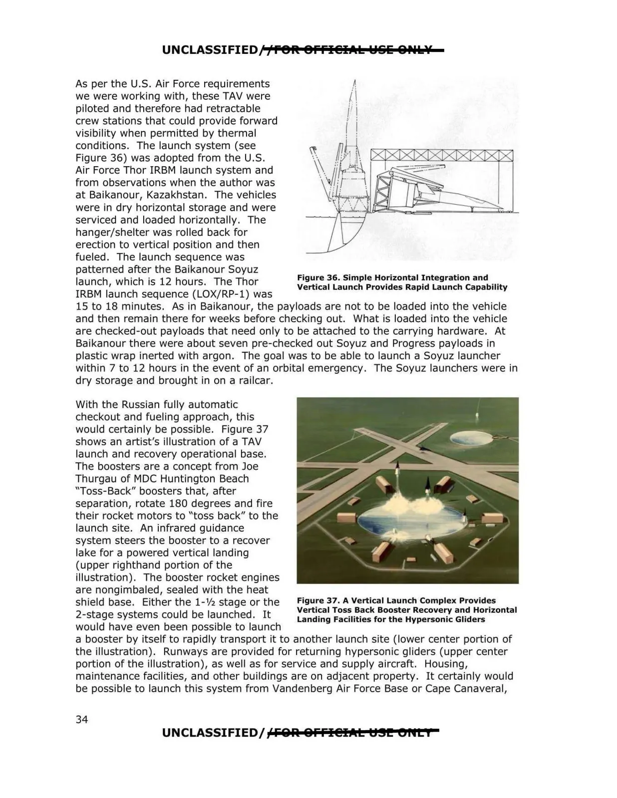
conditions. The launch system (see
Figure 36) was adopted from the U.S.
Air Force Thor IRBM launch system and
from observations when the author was
at Baikanour, Kazakhstan. The vehicles
were in dry horizontal storage and were
serviced and loaded horizontally. The
hanger/shelter was rolled back for
erection to vertical position and then
fueled. The launch sequence was
patterned atter the Baikanour Soyuz
Figure 36. Simple Horizontal Integration and
launch, which is 12 hours. The Thor
Vertical Launch Provides Rapid Launch Capability
IRBM launch sequence (LOX/RP-1) was
15 to 18 minutes. As in Baikanour, the payloads are not to be loaded into the vehicle
and then remain there for weeks before checking out. What is loaded into the vehicle
are checked-out payloads that need only to be attached to the carrying hardware. At
Baikanour there were about seven pre-checked out Soyuz and Progress payloads in
plastic wrap inerted with argon. The goal was to be able to launch a Soyuz launcher
within 7 to 12 hours in the event of an orbital emergency. The Soyuz launchers were in
dry storage and brought in on a railcar.
With the Russian fully automatic
checkout and fueling approach, this
would certainly be possible. Figure 37
shows an artist's illustration of a TAV
launch and recovery operational base.
The boosters are a concept from Joe
Thurgau of MDC Huntington Beach
"Toss-Back" boosters that, after
separation, rotate 180 degrees and fire
their rocket motors to "toss back" to the
launch site. An infrared guidance
system steers the booster to a recover
lake for a powered vertical landing
(upper righthand portion of the
illustration). The booster rocket engines
are nongimbaled, sealed with the heat
shield base. Either the 1-½ stage or the
2-stage systems could be launched. It
would have even been possible to launch
a booster by itself to rapidly transport it to another launch site (lower center portion of
the illustration). Runways are provided for returning hypersonic gliders (upper center
portion of the illustration), as well as for service and supply aircratt. Housing,
maintenance facilities, and other buildings are on adjacent property. It certainly would
be possible to launch this system from Vandenberg Air Force Base or Cape Canaveral,
UNCLASSIFIED/fFOlil &FFl@IAL U.!I!! t>IIL I
Figure 37. A Vertical Launch Complex Provides
Vertical Toss Back Booster Recovery and Horizontal
Landing Facilities for the Hypersonic Gliders
34