AAWSAP DIRD, Inertial Electrostatic Confinement Fusion, March 2010
DOW-UAP-D125 · page 18 of 72
Text
This text came with the file. It may have mistakes. When the text and the image disagree, the image is right.
UNCLASSIFIED//FOR 8FFI@IAL ~81!! 9HLY
the injected electrons so space charge neutralizatio111 can be achieved. This formalism is
then included as a boundary condition in a gridless particle code. Results indicate that
although the formalism works well during the early phases of compression, when the
compression gets large the solution bifurcates and becomes unphysical. Subsequent
experiments on POPS at Lawrence Livermore National Laboratory (LLNL) were
encouraging, but have not been continued at a high level of effort due to key staff
leaving for EMC2 . Thus, the practicality of this concept remains an open question which
deserves more research.
Miley's "Ion Injected" Device
The key to developing a IEC power device is to use external ion "guns" to form and
inj ect Ions into the spherical IEC chamber. This eliminates the need for a grid and
differential pumping between the gun and chamber allows the high vacuum needed in
the chamber. (Ion injection by external guns was originally used by Hirsch as already
noted. Also, more recently other labs, e.g. the University of Wisconsin and University of
Kyoto/Tokyo Institute of Technology, have started gun injection work. Some of that is
described later in this report) . The ion formation is done in the high pressure gun
discharge region outside of the chamber. Miley at UIUC (see Sections IV and VI) has
been studying such a system, both theoretically and experimentally. The theoretical
studies confirm that such an IEC plasma can exist stably and has sufficient confinement
time for aneutronic fusion. This assumes, however, very precise control is maintained
over the energy and angular momentum of injected ions and a balanced supply of
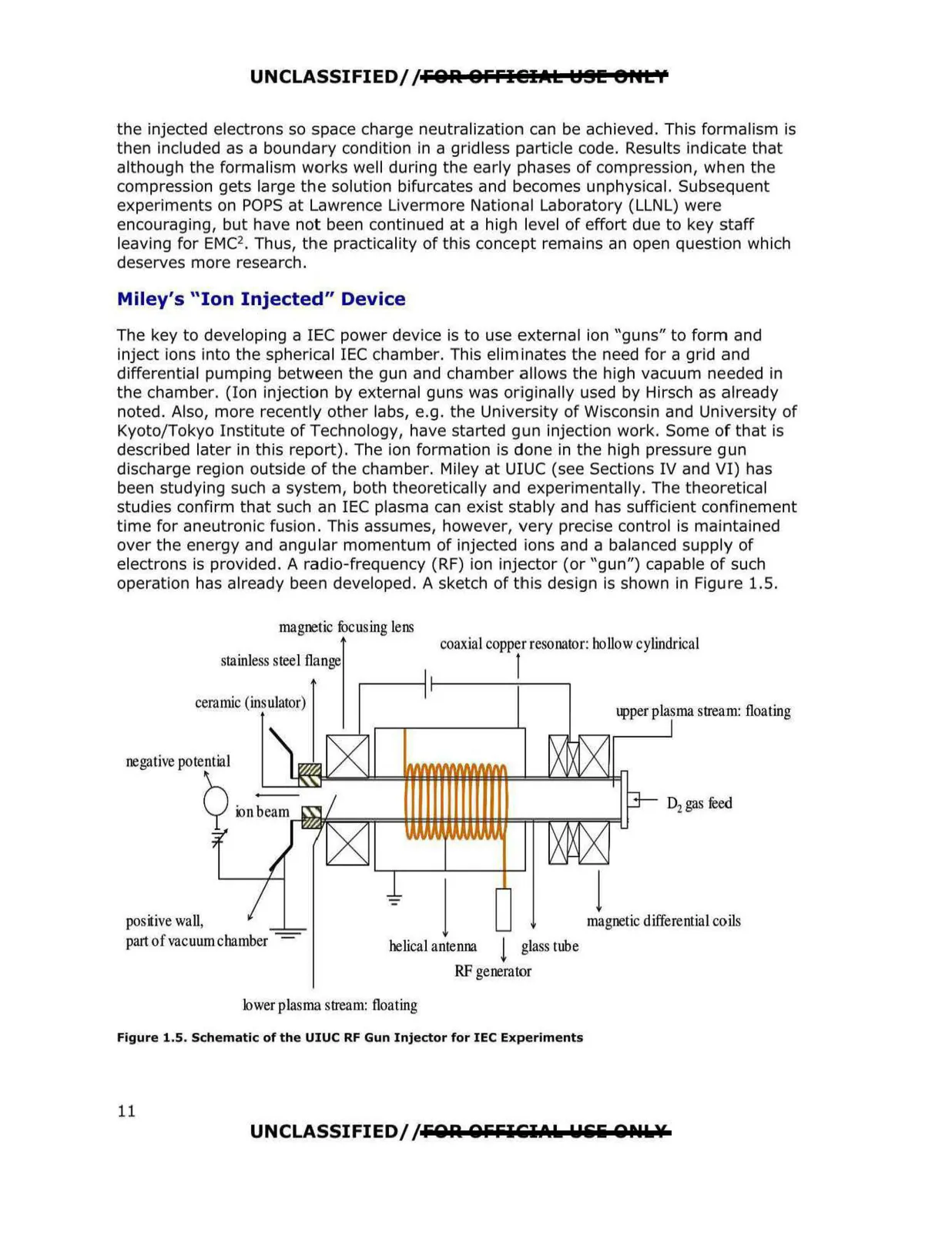
electrons is provided. A radio-frequency (RF) ion injector (or "gun") capable of such
operation has already been developed. A sketch of this design is shown in Figure 1.5.
magnetic focusing lens
stainless steel flange
ceramic (insulator)
negative potential
Q
~ nbeam~t,,J;,l;~==;:;===l:
positive wall,
part of vacuum chamber ~
t:t,:==;=f=i=r"iF=;;:=l
coaxial copper resonator: hollow cylindrical
l
upper plasma stream: floating
D2 gas feed
~l=t'A'Ft,VtJil/1t:tl't~l=l:~l4..,._
l
j
magnetic differential coils
helical antenna ! glass tube
RF generator
lower plasma stream: floating
Figure 1.5. Schematic of the UIUC RF Gun Injector for IEC Experiments
UNCLASSIFIED/ /FOA OFFI51Ak Wlili 0Plk¥
11