AAWSAP DIRD, Inertial Electrostatic Confinement Fusion, March 2010
DOW-UAP-D125 · page 34 of 72
Text
This text came with the file. It may have mistakes. When the text and the image disagree, the image is right.
UNCLASSIFIED//FOR OFFl@IAL ~SI: 8HLY
generation rate is achieved. The net accelerating voltage must be kept within the order
of 1 kV to ensure that the resultant exhaust velocity is in the range of 30,000 m/s (lsp
< 3000 seconds). The mission for a communications satellite is optimized with a
specific impulse in this range. A higher specific impulse would reduce propellant
requirements, but the power requirements and the mass associated with power source
components would increase correspondingly. Xenon is bled into the chamber through
holes at appropriate locations around the wall of the vessel.
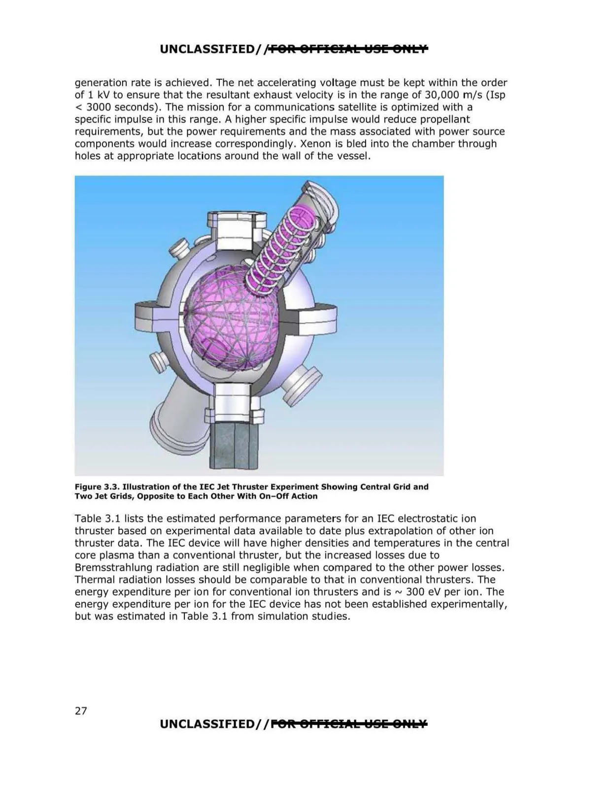
Figure 3.3. Illustration of the IEC Jet Thruster Experiment Showing Central Grid and
Two Jet Grids, Opposite to Each Other With On- Off Action
Table 3.1 lists the estimated performance parameters for an IEC electrostatic i-on
thruster based on experimental data available to date plus extrapolation of other ion
thruster data. The IEC device will have higher densities and temperatures in the central
core plasma than a conventional thruster, but the increased losses due to
Bremsstrahlung radiation are still negligible when compared to the other power losses.
Thermal radiation losses should be comparable to that in conventional thrusters. The
energy expenditure per ion for conventional ion thrusters and is ~300 eV per ion. The
energy expenditure per ion for the IEC device has not been established experimentally,
but was estimated in Table 3.1 from simulation studies.
UNCLASSIFIED/ /P"9K 8ffl@IAL ~SE ONLY
27