AAWSAP DIRD, Metallic Spintronics, March 2010
DOW-UAP-D129 · page 17 of 27
Text
This text came with the file. It may have mistakes. When the text and the image disagree, the image is right.
UNCLASSIFIED//FOA OFFl&ilAk Wfi& 8Ptl1f
3.4 STT-DRIVEN MOTION OF MAGNETIC DOMAIN WALLS
Yet another manifestation of STT in metallic ferromagnets is a motion of magnetic
domain walls traversed by an electrical current. The original prediction of the effect
dates back to 1978, when Luc Berger predicted that a spin-polarized current should
apply a torque to a magnetic domain wall (Reference 59). In a series of remarkable but
only recently appreciated works, Berger set the theoretical (Reference 59-62) and
experimental (Reference 63-65) groundwork for current-induced domain wall motion
(CIDWM), which is now documented in materials ranging from magnetic
semiconductors (Reference 66) to perpendicular-anisotropy superlattices (Reference
67). But the most widely studied materials by far have been metallic ferromagnets
(Reference 10, 11, 68-82), including Py (Nis1Fe19), CoFe, and Co, because of their
decades-long ubiquity in magnetic storage technology.
The CIDWM effect can be qualitatively understood on the basis of the following
arguments. Consider an electrical current flowing between two magnetic domains (A
and B) with opposite magnetizations and, thus, traversing a 180-degree magnetic
domain wall. The situation is similar to that of a single N/F interface discussed in
Section 3.1. While in domain A, spins of conduction electrons are preferentially aligned
with the magnetic moment of A. Once into domain B, the spins reverse to align with the
moment of B. In reversing the electron spins, magnetic moments in the domain wall
experience a torque associated with the change in angular momentum that occurs from
the rotation of electrons spins. This spin-transfer torque can move the domain wall in
the direction of the electron flow.
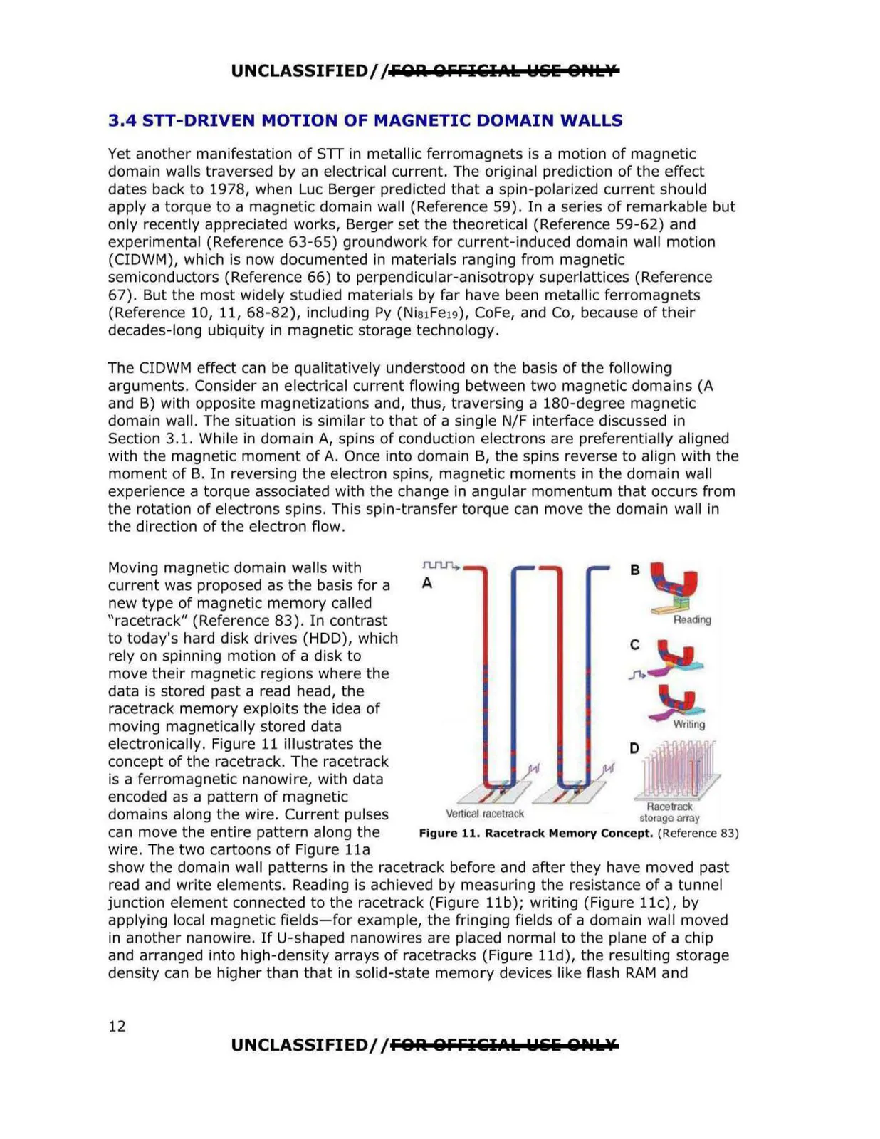
Moving magnetic domain walls with
n.rtJ1+
current was proposed as the basis for a
A
new type of magnetic memory called
"racetrack" (Reference 83 ). In contrast
to today's hard disk drives (HDD), which
rely on spinning motion of a disk to
move their magnetic regions where the
data is stored past a read head, the
racetrack memory exploits the idea of
moving magnetically stored data
electronically. Figure 11 illustrates the
concept of the racetrack. The racetrack
is a ferromagnetic nanowire, with data
encoded as a pattern of magnetic
Raal'track
domains along the wire. Current pulses
vertJcal race1rack
storage array
can move the entire pattern along the
Figure 11. Racetrack Memory Concept. (Reference 83)
wire. The two cartoons of Figure lla
show the domain wall patterns in the racetrack before and after they have moved past
read and write elements. Reading is achieved by measuring the resistance of a tunnel
junction element connected to the racetrack (Figure llb); writing (Figure llc), by
applying local magnetic fields-for example, the fringing fields of a domain wall moved
in another nanowire. If U-shaped nanowires are placed normal to the plane of a chip
and arranged into high-density arrays of racetracks (Figure lld), the resulting storage
density can be higher than that in solid-state memory devices like flash RAM and
B
C
fa
D
]I
UNCLASSIFIED//FOR OFFl&iilAk Wili 0Plk¥
12