AAWSAP DIRD, Technological Approaches to Controlling External Devices, March 2010
DOW-UAP-D130 · page 23 of 36
Text
This text came with the file. It may have mistakes. When the text and the image disagree, the image is right.
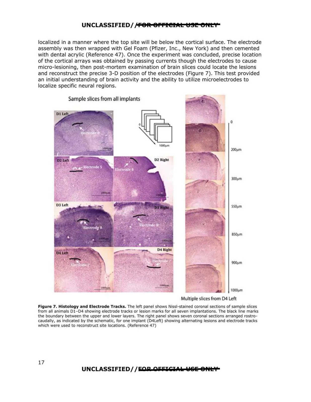
UNCLASSIFIED/,'FOR: 8Ffl@IJltt t:191!! er•t I localized in a manner where the top site will be below the cortical surface. The electrode assembly was then wrapped with Gel Foam (Pfizer, I nc. , New York) and then cemented with dental acrylic (Reference 47). Once the experiment was concluded, precise location of the cortical arrays was obtained by passing currents though the electrodes to cause micro-lesioning, then post-mortem examination of brain slices could locate the lesions and reconstruct the precise 3-D position of the electrodes (Figure 7). This test provided an initial understanding of brain activity and the ability to utilize microelectrodes to localize specific neural regions. Sample slices from all implants IOOOl)m Multipl sllces from 04 Left Figure 7. Histology and Electrode Tracks. The left panel shows Nissl-stained coronal sections of sample slices from all animals D1-D4 showing electrode tracks or lesion marks for all seven implantations. The black line marks the boundary between the upper and lower layers. The right panel shows seven coronal sections arranged rostro caudally, as indicated by the schematic, for one implant (D4Leh) showing alternating lesions and electrode tracks which were used to reconstruct site locations. (Reference 47) UNCLASSIFIED//EAR AfifilCl.\k Wlilii o ..tv 17