AAWSAP DIRD, Technological Approaches to Controlling External Devices, March 2010
DOW-UAP-D130 · page 24 of 36
Text
This text came with the file. It may have mistakes. When the text and the image disagree, the image is right.
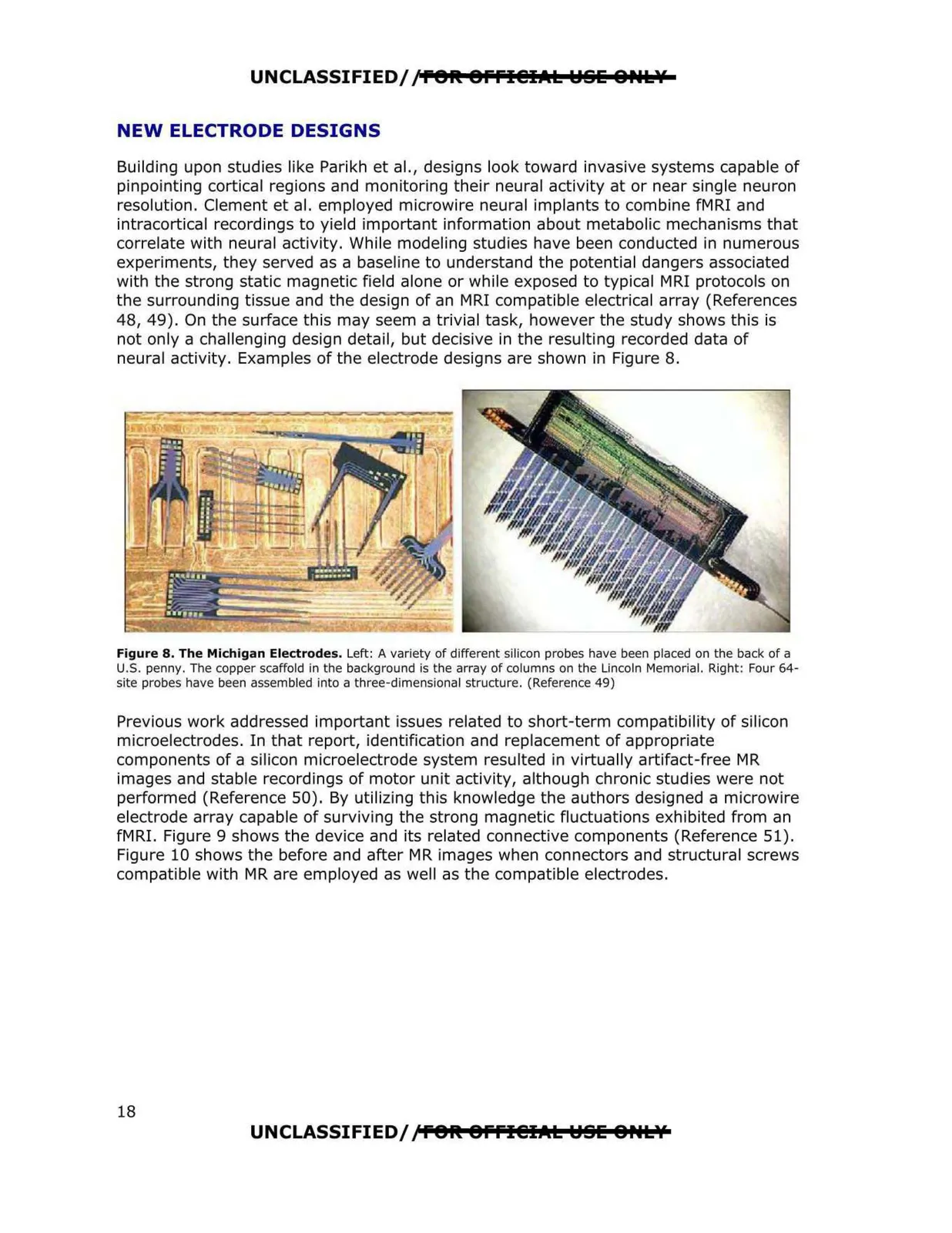
UNCLASSIFIED//P91t 9ffl@IAL YSE &P•tlf NEW ELECTRODE DESIGNS Building upon studies like Parikh et al., designs look toward invasive systems capable of pinpointing cortical regions and monitoring their neural activity at or near single neuron resolution. Clement et al. employed microwire neural implants to combine fMRI and intracortical recordings to yield important information about metabolic mechanisms that correlate with neural activity. While modeling studies have been conducted in numerous experiments, they served as a baseline to understand the potential dangers associated with the strong static magnetic field alone or while exposed to typical MRI protocols on the surrounding tissue and the design of an MRI compatible electrical array (References 48, 49). On the surface this may seem a trivial task, however the study shows this is not only a challenging design detail, but decisive in the resulting recorded data of neural activity. Examples of the electrode designs are shown in Figure 8. Figure 8. The Michigan Electrodes. Left: A variety of different silicon probes have been placed on the back of a U.S. penny. The copper scaffold in the background is the array of columns on the Lincoln Memorial. Right: Four 64 site probes have been assembled into a three-dimensional structure. (Reference 49) Previous work addressed important issues related to short-term compatibility of silicon microelectrodes. In that report, identification and replacement of appropriate components of a silicon microelectrode system resulted in virtually artifact-free MR images and stable recordings of motor unit activity, although chronic studies were not performed (Reference 50). By utilizing this knowledge the authors designed a microwire electrode array capable of surviving the strong magnetic fluctuations exhibited from an fMRI. Figure 9 shows the device and its related connective components (Reference 51). Figure 10 shows the before and after MR images when connectors and structural screws compatible with MR are employed as well as the compatible electrodes. UNCLASSIFIED//f91t 9ffl@IAL Y§E 8Htlf 18