AAWSAP DIRD, High-Frequency Gravitational Wave Communications, April 2010
DOW-UAP-D140 · page 14 of 57
Text
This text came with the file. It may have mistakes. When the text and the image disagree, the image is right.
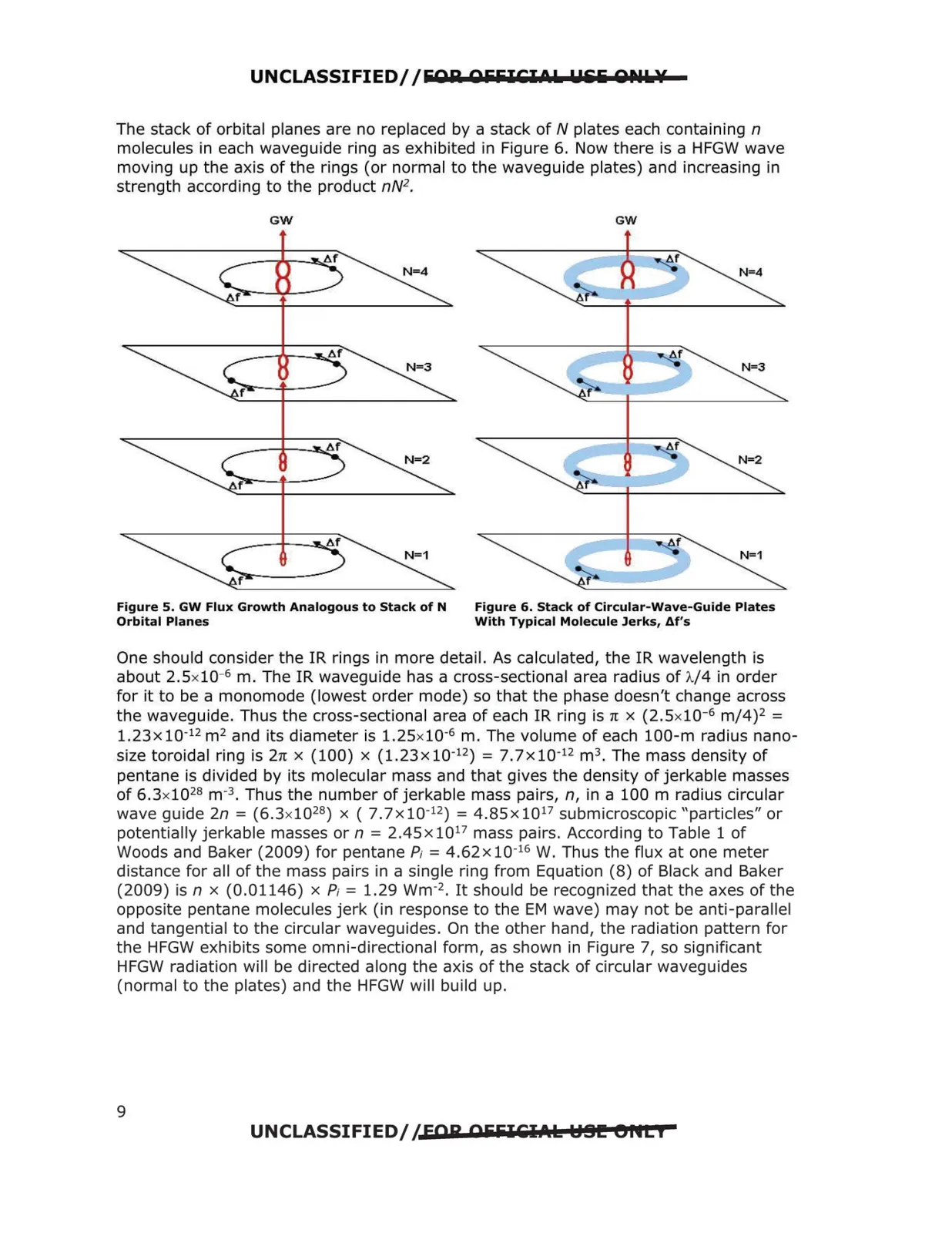
UNCLASSIFIED//&Olil OiiiilCI0L Llili QPIL¥ The stack of orbital planes are no replaced by a stack of N plates each containing n molecules in each waveguide ring as exhibited in Figure 6. Now there is a HFGW wave moving up the axis of the rings (or normal to the waveguide plates) and increasing in strength according to the product nN2 . GW GW Figure 5. GW Flux Growth Analogous to Stack of N Figure 6. Stack of Circular-Wave-Guide Plates Orbital Planes With Typical Molecule Jerks, df's One should consider the IR rings in more detail. As calculated, the IR wavelength is about 2.Sx10· 6 m. The IR waveguide has a cross-sectional area radius of A/4 in order for it to be a monomode (lowest order mode) so that the phase doesn't change across the waveguide. Thus the cross-sectional area of each IR ring is n x (2.Sx10·6 m/4)2 = l.23x 10-12 m2 and its diameter is 1.25xl0-6 m. The volume of each 100-m radius nano size toroidal ring is 2n x (100) x (1.23x 10-12) = 7. 7x 10-12 m3 . The mass density of pentane is divided by its molecular mass and that gives the density of jerkable masses of 6.3x1028 m·3. Thus the number of jerkable mass pairs, n, in a 100 m radius circular wave guide 2n = (6.3xl028) x ( 7.7x 10⁻¹²) = 4.85x10¹⁷ submicroscopic "particles" or potentially jerkable masses or n = 2.45 x 10¹⁷ mass pairs. According to Table 1 of Woods and Baker (2009) for pentane A= 4.62x 10⁻¹⁶ W. Thus the flux at one meter distance for all of the mass pairs in a single ring from Equation (8) of Black and Baker (2009) is n x (0.01146) x P; = 1.29 wm-2• It should be recognized that the axes of the opposite pentane molecules jerk (in response to the EM wave) may not be anti-parallel and tangential to the circular waveguides. On the other hand, the radiation pattern for the HFGW exhibits some omni-directional form, as shown in Figure 7, so significant HFGW radiation will be directed along the axis of the stack of circular waveguides (normal to the plates) and the HFGW will build up. UNCLASSIFIED//FOR OiiiilCl.t.k HSI!! eflti 9