AAWSAP DIRD, High-Frequency Gravitational Wave Communications, April 2010
DOW-UAP-D140 · page 29 of 57
Text
This text came with the file. It may have mistakes. When the text and the image disagree, the image is right.
UNCLASSIFIED/ /iiOR OiiiilCI O L lallili QPIL¥
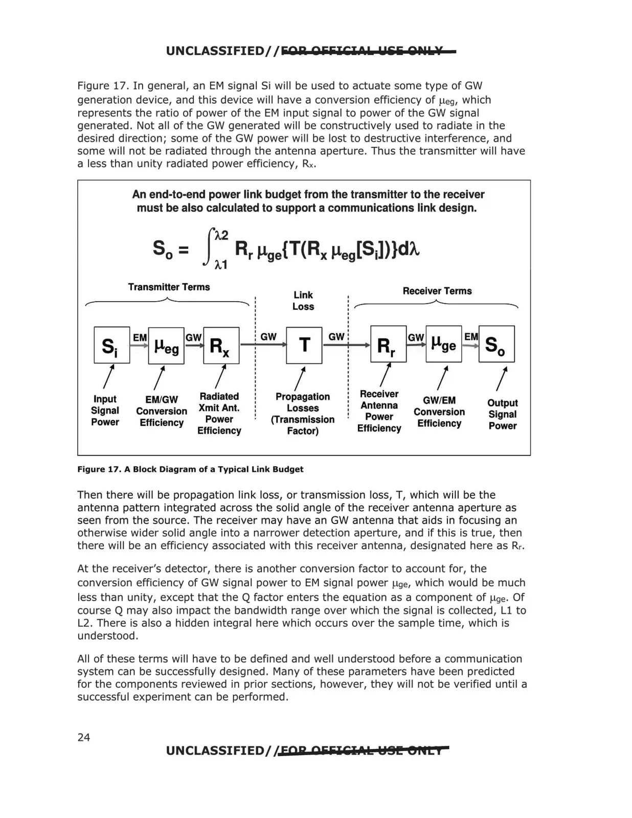
Figure 17. In general, an EM signal Si will be used to actuate some type of GW
generation device, and this device will have a conversion efficiency of µeg, which
represents the ratio of power of the EM input signal to power of the GW signal
generated. Not all of the GW generated will be constructively used to radiate in the
desired direction; some of the GW power will be lost to destructive interference, and
some will not be radiated through the antenna aperture. Thus the transmitter will have
a less than unity radiated power efficiency, Rx.
----
An end-to-end power link budget from the transmitter to the receiver
must be also calculated to support a communications link design.
Transmitter Terms
Receiver Terms
Link
A
r
--..
Loss
r
~
GW
GW µge
T
E~ So I
Rr
isi M~eg 1G~1 j I
GW
I
I
I
I
I
Receiver
Input
EM/GW
Radiated
Propagation
GW/EM
Output
Antenna
Xmit Ant.
Losses
Signal
Conversion
Conversion
Signal
:
Power
Power
(Transmission
Power
Efficiency
Efficiency
Power
Efficiency
Factor)
Efficiency
Figure 17. A Block Diagram of a Typical Link Budget
Then there will be propagation link loss, or transmission loss, T, which will be the
antenna pattern integrated across the solid angle of the receiver antenna aperture as
seen from the source. The receiver may have an GW antenna that aids in focusing an
otherwise wider solid angle into a narrower detection aperture, and if this is true, then
there will be an efficiency associated with this receiver antenna, designated here as Rr.
At the receiver's detector, there is another conversion factor to account for, the
conversion efficiency of GW signal power to EM signa l power µ9e, which would be much
less than unity, except that the Q factor enters the equation as a component of µ9e. Of
course Q may also impact the bandwidth range over which the signal is collected, Ll to
L2. There is also a hidden integral here which occurs over the sample time, which is
understood.
Al l of these terms will have to be defined and well understood before a communication
system can be successfully designed. Many of these parameters have been predicted
for the components reviewed in prior sections, however, they will not be verified until a
successful experiment can be performed.
UNCLASSIFIED/ / FOR OiiiilCl.t.k HSI!! eflti
24