AAWSAP DIRD, High-Frequency Gravitational Wave Communications, April 2010
DOW-UAP-D140 · page 30 of 57
Text
This text came with the file. It may have mistakes. When the text and the image disagree, the image is right.
UNCLASSIFIED//iiOlil OiiiilCI0L Llili QPIL¥
3.2 BANDWIDTH
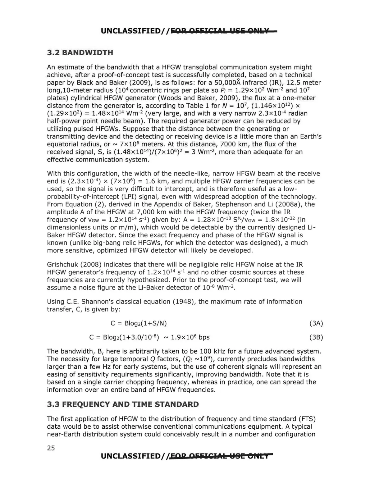
An estimate of the bandwidth that a HFGW transglobal communication system might
achieve, after a proof-of-concept test is successfully completed, based on a technical
paper by Black and Baker (2009), is as follows: for a 50,000..&. infrared (IR), 12.5 meter
long,10-meter radius {104concentric rings per plate so P; = l.29x 102 wm·2 and 107
plates) cylindrical HFGW generator (Woods and Baker, 2009), the flux at a one-meter
distance from the generator is, according to Table 1 for N = 107, (1.146x 1012) x
(1.29x102) = 1.48x1014 wm·2 (very large, and with a very narrow 2.3x10⁻⁴ radian
half-power point needle beam). The required generator power can be reduced by
utilizing pulsed HFGWs. Suppose that the distance between the generating or
transmitting device and the detecting or receiving device is a little more than an Earth's
equatorial radius, or~ 7x 10⁶ meters. At this distance, 7000 km, the flux of the
received signal, S, is (1.48x10¹⁴)/(7x106) 2 = 3 wm·2, more than adequate for an
effective communication system.
With this configuration, the width of the needle-like, narrow HFGW beam at the receive
end is (2.3x 10·4) x (7x 106) = 1.6 km, and multiple HFGW carrier frequencies can be
used, so the signal is very difficult to intercept, and is therefore useful as a low
probability-of-intercept (LPI) signal, even with widespread adoption of the technology.
From Equation (2), derived in the Appendix of Baker, Stephenson and Li (2008a), the
amplitude A of the HFGW at 7,000 km with the HFGW frequency (twice the IR
frequency of VGw = l.2x 1014 s·1) given by: A = l.28x 10-18 S½/VGw = l.8x 10-32 (in
dimensionless units or m/m), which would be detectable by the currently designed Li
Baker HFGW detector. Since the exact frequency and phase of the HFGW signal is
known (unlike big-bang relic HFGWs, for which the detector was designed), a much
more sensitive, optimized HFGW detector will likely be developed.
Grishchuk (2008) indicates that there will be negligible relic HFGW noise at the IR
HFGW generator's frequency of l.2x 1014 s·1 and no other cosmic sources at these
frequencies are currently hypothesized. Prior to the proof-of-concept test, we will
assume a noise figure at the Li-Baker detector of 10·8 wm-2.
Using C.E. Shannon's classical equation (1948), the maximum rate of information
transfer, C, is given by:
C = Blog2(l+S/N)
(3A)
C = Blog2(1+3.0/10·8) ~ 1.9x 10⁶ bps
(3B)
The bandwidth, B, here is arbitrarily taken to be 100 kHz for a future advanced system .
The necessity for large temporal Q factors, (Qt ~109), currently precludes bandwidths
larger than a few Hz for early systems, but the use of coherent signals will represent an
easing of sensitivity requirements significantly, improving bandwidth. Note that it is
based on a single carrier chopping frequency, whereas in practice, one can spread the
information over an entire band of HFGW frequencies.
3.3 FREQUENCY AND TIME STANDARD
The first application of HFGW to the distribution of frequency and time standard (FTS)
data would be to assist otherwise conventional communications equipment. A typical
near-Earth distribution system could conceivably result in a number and configuration
UNCLASSIFIED//FOR OiiiilCl.1.1: HSI! Bfltf
25