AAWSAP DIRD, High-Frequency Gravitational Wave Communications, April 2010
DOW-UAP-D140 · page 4 of 57
Text
This text came with the file. It may have mistakes. When the text and the image disagree, the image is right.
UNCLASSIFIED//iiOlil OiiiilCI0L Llili QPIL¥
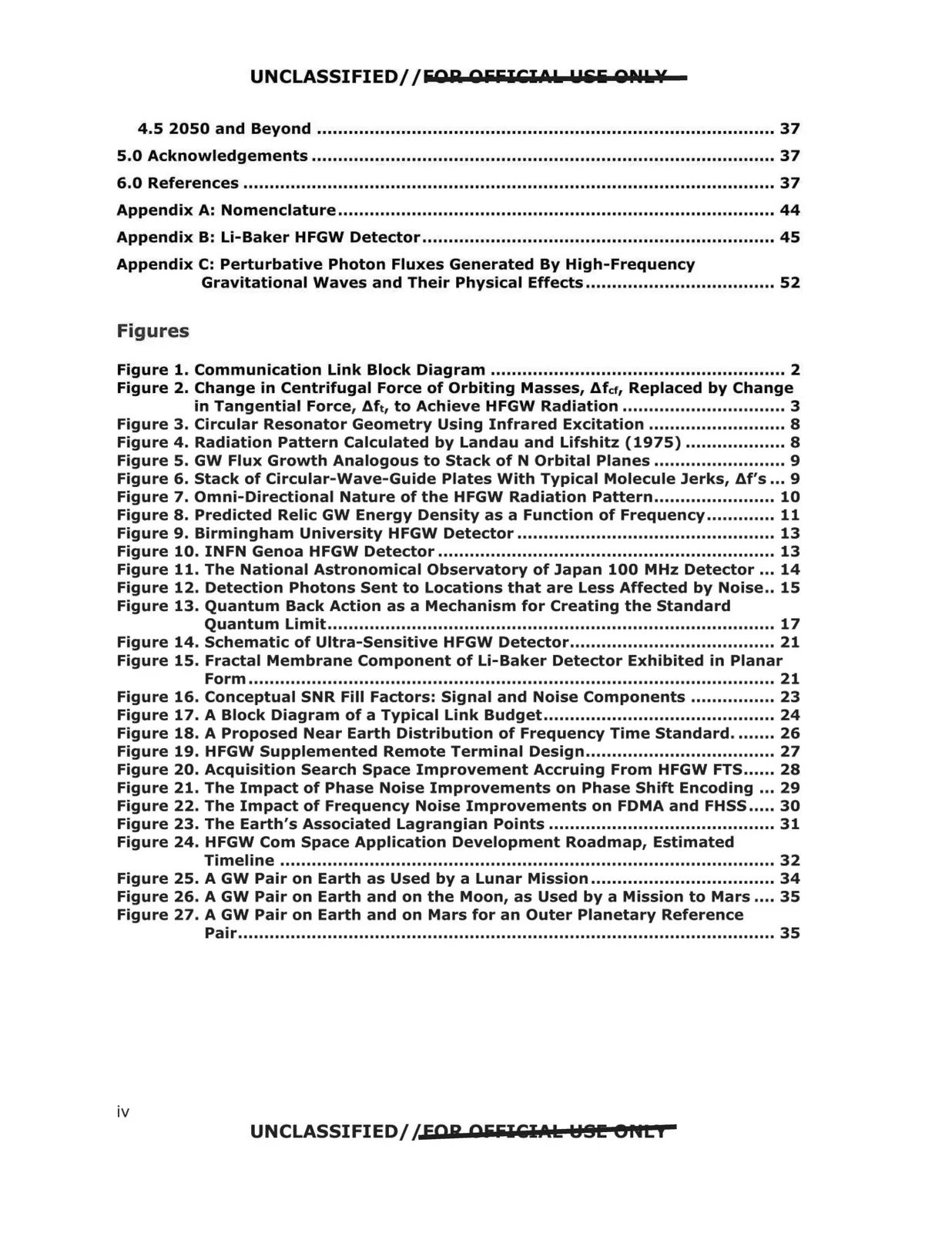
4.5 2050 and Beyond ....................................................................................... 37
5.0 Acknowledgements ........................................................................................ 37
6.0 References ..................................................................................................... 37
Appendix A: Nomenclature ................................................................................... 44
Appendix B: Li-Baker HFGW Detector................................................................... 45
Appendix C: Perturbative Photon Fluxes Generated By High-Frequency
Gravitational Waves and Their Physical Effects .................................... 52
Figures
Figure 1. Communication Link Block Diagram ........................................................ 2
Figure 2. Change in Centrifugal Force of Orbiting Masses, Afct, Replaced by Change
Figure 13. Quantum Back Action as a Mechanism for Creating the Standard
Figure 15. Fractal Membrane Component of Li-Baker Detector Exhibited in Planar
Figure 24. HFGW Com Space Application Development Roadmap, Estimated
Figure 27. A GW Pair on Earth and on Mars for an Outer Planetary Reference
in Tangential Force, '1ft, to Achieve HFGW Radiation ............................... 3
Figure 3. Circular Resonator Geometry Using Infrared Excitation .......................... 8
Figure 4. Radiation Pattern Calculated by Landau and Lifshitz (1975) ................... 8
Figure 5. GW Flux Growth Analogous to Stack of N Orbital Planes ......................... 9
Figure 6. Stack of Circular-Wave-Guide Plates With Typical Molecule Jerks, Af's ... 9
Figure 7. Omni-Directional Nature of the HFGW Radiation Pattern....................... 10
Figure 8. Predicted Relic GW Energy Density as a Function of Frequency............. 11
Figure 9. Birmingham University HFGW Detector ................................................. 13
Figure 10. INFN Genoa HFGW Detector ................................................................ 13
Figure 11. The National Astronomical Observatory of Japan 100 MHz Detector ... 14
Figure 12. Detection Photons Sent to Locations that are Less Affected by Noise.. 15
Quantum Limit..................................................................................... 17
Figure 14. Schematic of Ultra-Sensitive HFGW Detector....................................... 21
Form .................................................................................................... 21
Figure 16. Conceptual SNR Fill Factors: Signal and Noise Components ................ 23
Figure 17. A Block Diagram of a Typical Link Budget............................................ 24
Figure 18. A Proposed Near Earth Distribution of Frequency Time Standard........ 26
Figure 19. HFGW Supplemented Remote Terminal Design.................................... 27
Figure 20. Acquisition Search Space Improvement Accruing From HFGW FTS ...... 28
Figure 21. The Impact of Phase Noise Improvements on Phase Shift Encoding ... 29
Figure 22. The Impact of Frequency Noise Improvements on FDMA and FHSS ..... 30
Figure 23. The Earth's Associated Lagrangian Points ........................................... 31
Timeline .............................................................................................. 32
Figure 25. A GW Pair on Earth as Used by a Lunar Mission ................................... 34
Figure 26. A GW Pair on Earth and on the Moon, as Used by a Mission to Mars .... 35
Pair...................................................................................................... 35
UNCLASSIFIED//FOR OiiiilCl.t.k HSI!! eflti
iv