AAWSAP DIRD, Metamaterials for Aerospace Applications, April 2010
DOW-UAP-D141 · page 17 of 38
Text
This text came with the file. It may have mistakes. When the text and the image disagree, the image is right.
.
·,
'
:
:
~ ·~t~=~- :~
'
•··-·
UNCLASSIFIED/ (FOR OFEICI0k YSE 8Htt
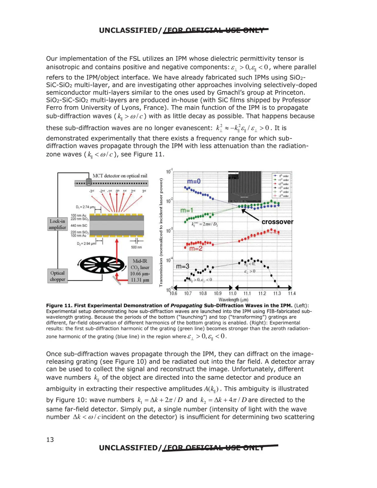
Our implementation of the FSL utilizes an 1PM whose dielectric permittivity tensor is
anisotropic and contains positive and negative components: c1_ > 0,c11 < 0, where parallel
refers to the !PM/object interface. We have already fabricated such IPMs using SiO2
SiC-SiO2 multi-layer, and are investigating other approaches involving selectively-doped
semiconductor multi-layers similar to the ones used by Gmachl's group at Princeton.
SiO2-SiC-SiO2 multi-layers are produced in-house (with SiC films shipped by Professor
Ferro from University of Lyons, France). The main function of the 1PM is to propagate
sub-diffraction waves ( "ii > wl c) with as little decay as possible. That happens because
these sub-diffraction waves are no longer evanescent: k1 ~ -kI~&11 I &1- > 0. It is
demonstrated experimentally that there exists a frequency range for which sub
diffraction waves propagate through the 1PM with less attenuation than the radiation
zone waves ( "ii < w/ c ), see Figure 11.
MCT detector on optical rail
~
0.
,.,,.: ~r~~
«)
100nmAll
,-L
-in-, 220nm Si02
-oc~·k-
2.94 µml-J
i
~
IO r;:t ~r~~ros~::,
amplifier
440 nm SiC
£
;
II
1!
220 nm 00,
«)
100 nm All
"
-~
01=
iii
!tt··=
500nm
§
- 2'
• -r--·
0
-
'
C
.
~
--+----
•
:j 10
j~
t--~-
.
Optical
chopp.:i-
~
,-<.U.
i=
.5
:
1010.6
10.7
10.8
10.9
11.0
11.1
11.2
11.3
11.4
Wavelength (µm)
Figure 11. First Experimental Demonstration of Propagating Sub-Diffraction Waves in the 1PM. (Left):
Experimental setup demonstrating how sub-diffraction waves are launched into the 1PM using FIB-fabricated sub
wavelength grating. Because the periods of the bottom ("launching") and top ("transforming") gratings are
different, far-field observation of different harmonics of the bottom grating is enabled. (Right): Experimental
results: the first sub-diffraction harmonic of the grating (green line) becomes stronger than the zeroth radiation-
zone harmonic of the grating (blue line) in the region where£1- > 0, &11 < 0 .
Once sub-diffraction waves propagate through the 1PM, they can diffract on the image
releasing grating (see Figure 10) and be radiated out into the far field. A detector array
can be used to collect the signal and reconstruct the image. Unfortunately, different
wave numbers k 11 of the object are directed into the same detector and produce an
ambiguity in extracting their respective amplitudes A(k11 ). This ambiguity is illustrated
by Figure 10: wave numbers k1 = tik + 21r ID and k2 = M + 41r ID are directed to the
same far-field detector. Simply put, a single number (intensity of light with the wave
number tik < w I c incident on the detector) is insufficient for determining two scattering
13
UNCLASSIFIED/ {fQR OFEICl.t.ls: Y81!! 8flti
-
--t;aa-'-------,----------,----
-···-··-:-·· ...-~--,
-2
:i===:==~·~St~