AAWSAP DIRD, Metamaterials for Aerospace Applications, April 2010
DOW-UAP-D141 · page 18 of 38
Text
This text came with the file. It may have mistakes. When the text and the image disagree, the image is right.
UNCLASSIFIED/ (fQR OFFIClt.k YSE 8HLI
amplitudes ( A(k1) and A(k2 ) ). Therefore, a new concept has to be developed, and the
multi-detector technique is such a concept.
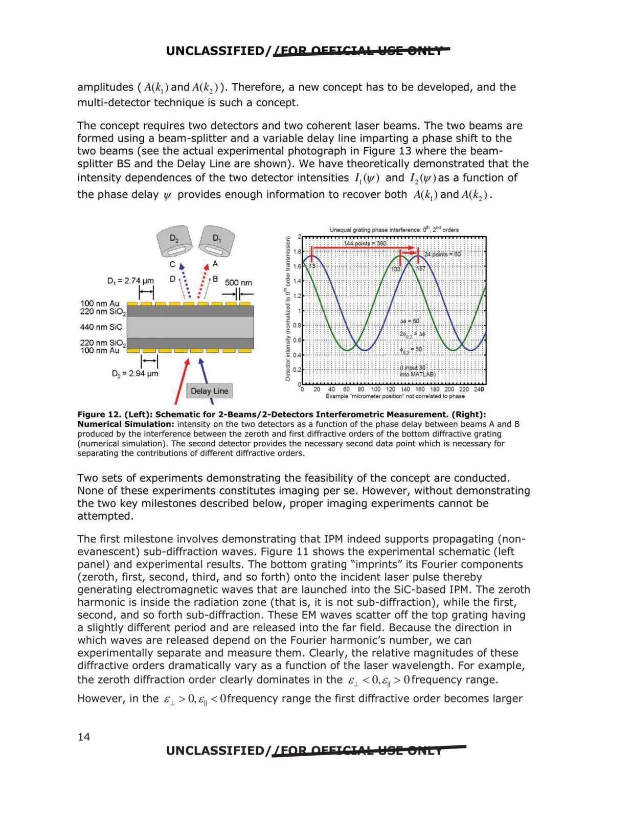
The concept requires two detectors and two coherent laser beams. The two beams are
formed using a beam-splitter and a variable delay line imparting a phase shift to the
two beams (see the actual experimental photograph in Figure 13 where the beam
splitter BS and the Delay Line are shown). We have theoretically demonstrated that the
intensity dependences of the two detector intensities / 1(1/1) and / 2 (1/f) as a function of
the phase delay 1/f provides enough information to recover both A(k1) and A(k2) .
Unequal grating phase interference: dh, t ld orders
D1 = 2.74 µmH
100 nm Au
220 nm Si02
440 nm SiC
220 nm SiO2
100 nm Au
-
. ·
0o
20
40
60
BO
100 120 140 160 180 200 220 240
Example "micrometer position" not correlated lo phase
Figure 12. (Left): Schematic for 2-Beams/2-Detectors Interferometric Measurement. (Right):
Numerical Simulation: intensity on the two detectors as a function of the phase delay between beams A and B
produced by the interference between the zeroth and first diffractive orders of the bottom diffractive grating
(numerical simulation). The second detector provides the necessary second data point which is necessary for
separating the contributions of different diffractive orders.
Two sets of experiments demonstrating the feasibility of the concept are conducted.
None of these experiments constitutes imaging per se. However, without demonstrating
the two key milestones described below, proper imaging experiments cannot be
attempted.
The first milestone involves demonstrating that 1PM indeed supports propagating (non
evanescent) sub-diffraction waves. Figure 11 shows the experimental schematic (left
panel) and experimental results. The bottom grating "imprints" its Fourier components
(zeroth, first, second, third, and so forth) onto the incident laser pulse thereby
generating electromagnetic waves that are launched into the SiC-based 1PM. The zeroth
harmonic is inside the radiation zone (that is, it is not sub-diffraction), while the first,
second, and so forth sub-diffraction. These EM waves scatter off the top grating having
a slightly different period and are released into the far field. Because the direction in
which waves are released depend on the Fourier harmonic's number, we can
experimentally separate and measure them. Clearly, the relative magnitudes of these
diffractive orders dramatically vary as a function of the laser wavelength. For example,
the zeroth diffraction order clearly dominates in the &J_ < 0,&11 > Ofrequency range.
However, in the sj_ > 0, s11 < Ofrequency range the first diffractive order becomes larger
UNCLASSIFIED/ {fQR OFEICl.t.ls: W81!! 8flti
14