AAWSAP DIRD, Metamaterials for Aerospace Applications, April 2010
DOW-UAP-D141 · page 25 of 38
Text
This text came with the file. It may have mistakes. When the text and the image disagree, the image is right.
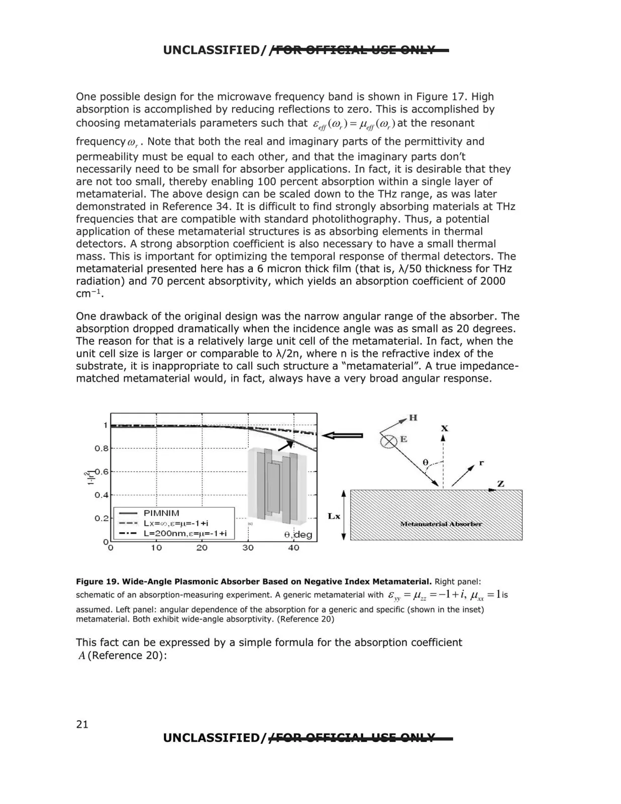
UNCLASSIFIED//POil Offl@IAI:: YS& 8Nl::\f One possible design for the microwave frequency band is shown in Figure 17. High absorption is accomplished by reducing reflections to zero. This is accomplished by choosing metamaterials parameters such that &eri@,.) =µ.1i@,. ) at the resonant frequency co,. . Note that both the real and imaginary parts of the permittivity and permeability must be equal to each other, and that the imaginary parts don't necessarily need to be small for absorber applications. In fact, it is desirable that they are not too small, thereby enabling 100 percent absorption within a single layer of metamaterial. The above design can be scaled down to the THz range, as was later demonstrated in Reference 34. It is difficult to find strongly absorbing materials at THz frequencies that are compatible with standard photolithography. Thus, a potential application of these metamaterial structures is as absorbing elements in thermal detectors. A strong absorption coefficient is also necessary to have a small thermal mass. This is important for optimizing the temporal response of thermal detectors. The metamaterial presented here has a 6 micron thick film (that is, )\/50 thickness for THz radiation) and 70 percent absorptivity, which yields an absorption coefficient of 2000 cm- 1 . One drawback of the original design was the narrow angular range of the absorber. The absorption dropped dramatically when the incidence angle was as small as 20 degrees. The reason for that is a relatively large unit cell of the metamaterial. In fact, when the unit cell size is larger or comparable to )IJ2n, where n is the refractive index of the substrate, it is inappropriate to call such structure a "metamaterial". A true impedance matched metamaterial would, in fact, always have a very broad angular response. ' . ' . H ' . --- - --- - --- -- - •-- - --- - ------- - •----- X . ' ' ! 0.8 --------------- 1---------------1---------------: . ' ~-6--------------- i -------------+------------- -0.4 -- --------- ----[ ---------------; ____ _________ __ PIMNIM Lx 0.2 L x= c,J.E=J.L=-1 +i L=200nm ,i::=1-L=-1 +i 10 20 30 40 Figure 19. Wide-Angle Plasmonic Absorber Based on Negative Index Metamaterial. Right panel: schematic of an absorption-measuring experiment. A generic metamaterial with 8 YY = f.l zz = - 1+i, f.lx., = l is assumed. Left panel : angular dependence of the absorption for a generic and specific (shown in the inset) metamaterial. Both exhibit wide-angle absorptivity. (Reference 20) This fact can be expressed by a simple formula for the absorption coefficient A (Reference 20): UNCLASSIFIED/fFOA OFFICilial.L. W&li OlhlL.¥ 21