AAWSAP DIRD, Aneutronic Fusion Propulsion II, November 2010
DOW-UAP-D146 · page 23 of 36
Text
This text came with the file. It may have mistakes. When the text and the image disagree, the image is right.
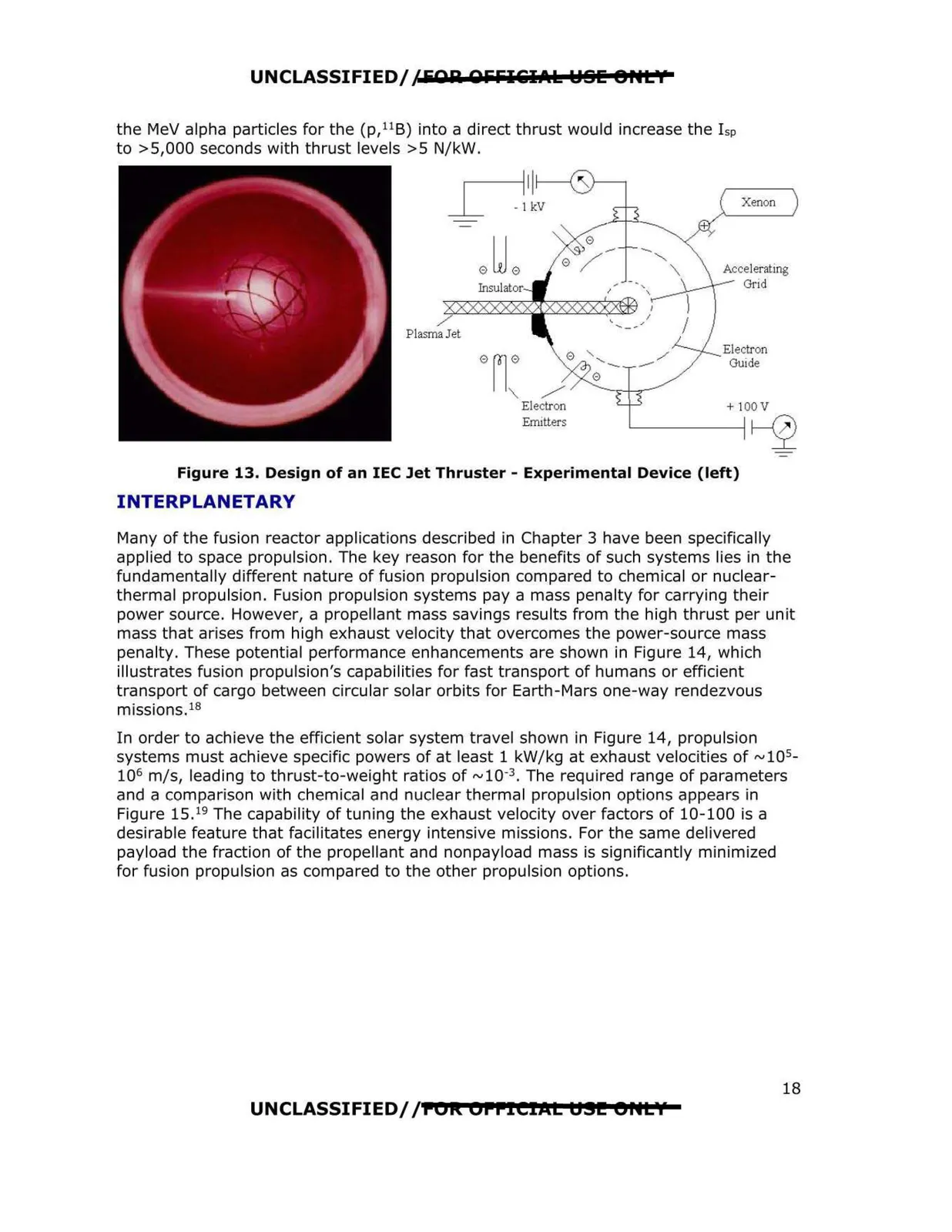
UNCLASSIFIED/ /FOR OFFI&IAl l::181: 8HL'f the MeV alpha particles for the (p, 11B) into a direct thrust would increase the l sp to >5,000 seconds with thrust levels >5 N/kW. Xenon / Plasma Jet Electron Guide 0ri: / 0------.,_--.i-.,.,- Electron + 100V Emitters ~ Figure 13. Design of an IEC Jet Thruster - Experimental Device (left) INTERPLANETARY Many of the fusion reactor applications described in Chapter 3 have been specifically applied to space propulsion. The key reason for the benefits of such systems lies in the fundamentally different nature of fusion propulsion compared to chemical or nuclear thermal propulsion. Fusion propulsion systems pay a mass penalty for carrying their power source. However, a propellant mass savings results from the high thrust per unit mass that arises from high exhaust velocity that overcomes the power-source mass penalty. These potential performance enhancements are shown in Figure 14, wh ich illustrates fusion propulsion's capabilities for fast transport of humans or efficient transport of cargo between circular solar orbits for Earth -Mars one-way rendezvous missions.18 In order to achieve the efficient solar system travel shown in Figure 14, propulsion systems must achieve specific powers of at least 1 kW/kg at exhaust velocities of ~105 106 m/s, leading to thrust-to-weight ratios of ~10-3 . The required range of parameters and a comparison with chemical and nuclear thermal propulsion options appears in Figure 15. 19 The capability of tuning the exhaust velocity over factors of 10- 100 is a desirable feature that facil itates energy intensive missions. For the same delivered payload the fraction of the propellant and nonpayload mass is significantly minimized for fusion propulsion as compared to the other propulsion options. UNCLASSIFIED/ /POI\ OPPICIAL U.!I!! er~t'I' 18