AAWSAP DIRD, Detection and High-Resolution Tracking of Vehicles at Hypersonic Velocities, November 2010
DOW-UAP-D148 · page 13 of 46
Text
This text came with the file. It may have mistakes. When the text and the image disagree, the image is right.
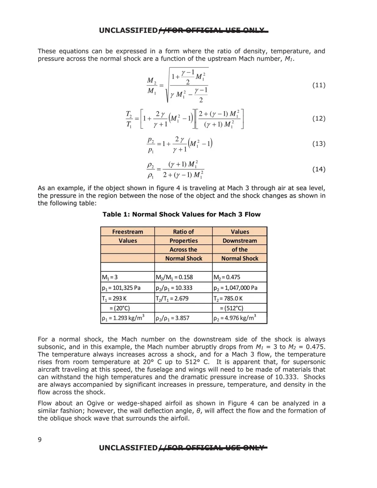
UNCLASSIFIED/fFOR. QFFIEIA.L: Ulii Qt!! X These equations can be expressed in a form where the ratio of density, temperature, and pressure across the normal shock are a function of the upstream Mach number, M1. (11) (12) Pz = 1+ ~(M12 - 1) (13) P1 r+ 1 Pi <r + t) M 12 = ---- (14) Pi 2 + (y - 1) M i2 As an example, if the object shown in figure 4 is traveling at Mach 3 through air at sea level, the pressure in the region between the nose of the object and the shock changes as shown in the following table: Table 1: Normal Shock Values for Mach 3 Flow Freestream Ratio of Values Values Properties Downstream Across the of the Normal Shock Normal Shock M1 =3 M2/M1 = 0.158 M2 = 0.475 p1 = 101,325 Pa p/p1 = 10.333 p2 = 1,047,000 Pa T1 = 293 K Ti/T1 = 2.679 T2 = 785.0 K = (2o·q = (s12·q p1 = 1.293 kg/m 3 p/p1 = 3.857 p2 = 4.976 kg/m3 For a normal shock, the Mach number on the downstream side of the shock is always subsonic, and in this example, the Mach number abruptly drops from M1 = 3 to M2 = 0.475. The temperature always increases across a shock, and for a Mach 3 flow, the temperature rises from room temperature at 20° C up to 512° C. It is apparent that, for supersonic aircraft traveling at this speed, the fuselage and wings will need to be made of materials that can withstand the high temperatures and the dramatic pressure increase of 10.333. Shocks are always accompanied by significant increases in pressure, temperature, and density in the flow across the shock. Flow about an Ogive or wedge-shaped airfoil as shown in Figure 4 can be analyzed in a similar fashion; however, the wall deflection angle, e, will affect the flow and the formation of the oblique shock wave that surrounds the airfoil. UNCLASSIFIED//EQA: QlililEl.t.L: W&&: O,.L'l 9