Project Sign Progress Report, 1948
DOW-UAP-D097 · page 44 of 45
Text
This text came with the file. It may have mistakes. When the text and the image disagree, the image is right.
THE AEROPLANE
. 338
MARCH 19, 1948
•
t
L
l
100 C
AR 1
LA> ...l'
1IO
~
--;? ~:a-: L-/
L,CI" ,_,...
f
i\ ~ ~ /
~ 100
I
- ,
AR~
...:z
~Vv
V
~
~
80
~ ~ ~" Lu
V
V
,.I.
00
,, '
t:
't..
::;
/
J v v l,o'
'°
1,,1" fif (r
l.,o'
~ v
.#J~
cf
1-► (l
10 °
10
o·
I
.,.
0 '
•NGt[ or INCll)[NC( ( O!GRCES i
10
...
~
aeroplane with take·off as helicopter {Brit.
Pat. Spec.
No.161,948). Earlier still (in 1916), the German, F. Bendemann,
a noted fesearcb worker on a1rscrews, conducted a secret
development of an aeroplane with a large tilting airscrew
capable of rising and descending as a helicopter.
The
development of this air observation post was later discon•
tinued in view ot the Austrian helicopter experiments by
Th. v. Karman and Petroczy.
From
his
early
experiments
with
lifting
airscrews,
F. Bendemann found that hoverihg without forward movement
could be achieved- when the power loading of the aircraft was
less than about 9 11,../ b.b-.p.
With fighter aeroplanes, such
low power loadings were already then being approached and
1
operational experience bad indeed shown that certain single·
sealers could. under favourable conditions, be held in attitudes
approaching that of hov.ering (later the Fokker D.Vll biplane,
with a large airscrew, became renowned for this trick 10 air
combat on the Western Front). Attempts to revive the project
~ta later date failed. and with the suicide of its promoter (who
had gone into the Civil Service), all interest lo the development
ceased.
•
Charles W. Zimmermann, mentioned earlier as stimulator of
the disc wing, approached the conception of the helicopter
Aeroplane on the basis of his results with low aspect ratio
wings.
He secured basic patents and constructed during
1934·35, in the cellar of his home, a man-carrying aircraft of
bis design.
This had a wing of only 7-ft. span, with two
airscrews driven by two 25 b.h.p. engines.
Due to persistent
engine trouble, no flights were made; the Little aircraft showed,
however. all the C$SCOtial features of the present types.
In 1937 he granted a licence for his patents to the Chance•
Vought Aircraft Division of the Unik:d Aircraft Corporation
in Strntfort, Connecticut, and /'oined this firm for the further
development of his ideas.
t is possible that the public
conception of the mysterious "Flying Saucers" has origmated
from this develo,,ment.
Zimmermann's intention may have been the development of
a safety-first aeroplaoe for the private owner.
The U.S. Navy,
however, took an interest in the possibilities of the helicopter•
aeroplane, and the work done at present is purely for military
purposes.
In 1942 a low-powered piloted scale model type
V-173 was constructed.
This wooden aircraft made many
flights and proved that the ideas underlying the design were
practical.
The principle is that, at high speed and when cruising, the
aircraft shall fty as an aeroplane, while for slow speed and
hovering it flies as a helicopter.
Hence the airscrews are at
the same time rotors and must have a rarher large diameter.
With the V-173 the problem of the prone position for the pilot
was studied. and there is reason to believe that the latest types
have adopted this feature.
A further step towards the realization of a naval gun-spotter
and a fia),ter for use from aircraft carriers bas been the Chance·
Vouaht XF5U·l single-seater (1946), for which a speed range
from 40 m.p.h. landing speed to over 425 m.p.h. has been
claimed; in general, it follows the V-173 model. (See p. 185,
February 13.)
The aspect ratio of the wing is lesa than unity.
Strictly
speaking, however, it is not a genuine tailless aeroplane because
of the attachment of a trimmmg elevator to both sides ot the
wina. The reason for such excrescences is the need to locate
I
I
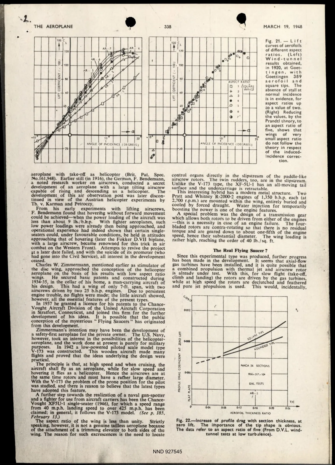
Fig. 21. -
LI ft
100 Cl
curves of aerofoils
t 1,10
--
of different aspect
ratios.
(Left)
~· O+
Wind -tunnel
-l
. o,."'
..
C
results obtained,
~- 100
in 1920, at Goet•
o"'f3.
I
tlngcn, w ith
I A .
Goettlngen
389
eo
~
ASPIC.T RATIO
aero fo i l and
~
a
1 Aou,hf
square t ips. The
0
?
WING
absence of stall at
t
V
00
+
,__ ,__
.0.
J
normal Incidence
::;
Is In evidence, for
b
• •
aspect ratios up
.o
I
,__
to a value of two.
I
t:
'° t
I+
..
ro
~
(Right) Reducing
() ,·
the values. by the
Prandtl theory.to
,,.
an aspect ratio of
five, shows t hat
wings
of
very
10 •
10
small aspect ratio
- - <
I
AN(;l[ Of tNCIO(N(( t OIGRH\ I
do not follow the
IO
theory in respect
of the induced
Incidence correc•
tlon.
control organs directly in the slipstream of tht: paddle-like
airscrew rotor... The twin rudders, too. are in the slipslfeam.
Unlike the V-173 type, the XF-SU· l has an all-moving tail
surface and the undercarriage is retractable.
This interesting hybrid has a modern metal structure.
Two
Pratt and Whilney R-2000-2 engines Qf 1,350 b.h.p. each (at
2,700 r.p.m.) are mounted within the wing, entirely buried and
cooled by forced draught.
Water injection for temporarily
boosting the oower is one of the engine features.
A special oroblem was the design of a transmission ~ear
which allows both rotors to be driven from either of the eogmes
- this is a necessity in case of an engine failure.
The four·
bladed rotors are contra-rotating so that there is no residual
torque and are ,eared down to about one-fifth of the engine
speed, hence their substanlial diameter.
The wing loading is
rather high. reaching the order of 40 lb./sq. ft.
The Real Flying Saucer ?
Since this experimental type was produced, further progress
has been made in the development.
IL seems that axial-flow
gas turbines have been installed, and it is quite possible that
a combined oropulsion with thermal jet and airscrew rotor
is alt:eadv under test.
Wilh this, for slow flight (take-off,
climb and landing) the rotors are driven by the gas turbines,
while at high speed the rotors are declutched and feathered
and pure jet propulsion is used.
This would, incidentally,
(
~01! 1---1---1------.1---1----1----1
;
0
~ -
,.
<
i
Q
:::
...
NACA 14 SEC11C)N:~
iS
V
..,
0-00,
._N•'1·1 , 10'
~
0
0.~L T!HI
i ,. ~
...
I
~
T{C
~ -
~01
0-ll
0-16
~IO
0 •1'
AU,0r0tL TMICKNESS A.ATIO
Fie. 22.-lncrease of profile drq with section thickness, at
:zero 11ft.
The lfnporunce of the tip shape Is obvious.
The data refer to an aspect ratio of flve (From D.V.L. wind-
tunnel tesu at low turbulence).
NND 927545