AAWSAP DIRD, Space Access: Where We’ve Been and Where We Could Go, March 2010
DOW-UAP-D124 · page 11 of 56
Text
This text came with the file. It may have mistakes. When the text and the image disagree, the image is right.
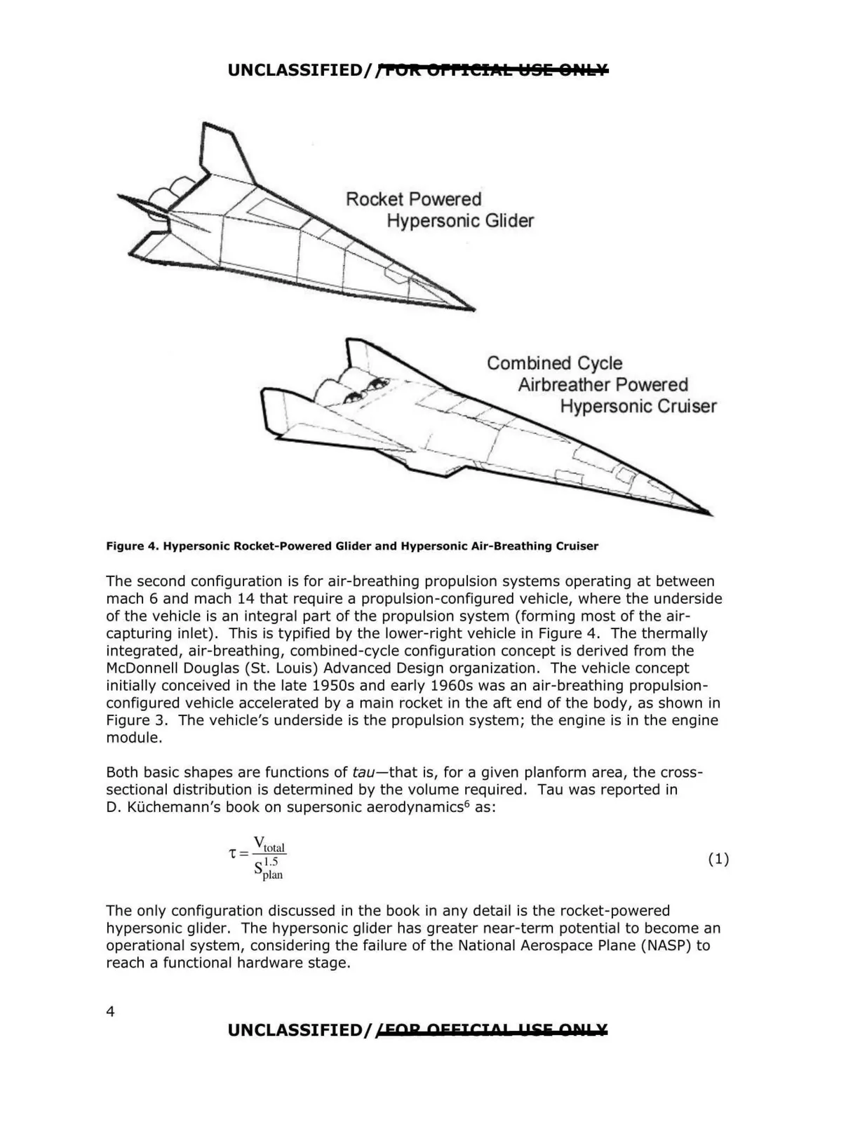
UNCLASSIFIED/JFOR OFFICIJltL YSE 8PUslf Rocket Powered Hypersonic Glider Combined Cycle Airbreather Powered Hypersonic Cruiser Figure 4. Hypersonic Rocket-Powered Glider and Hypersonic Air-Breathing Cruiser The second configuration is for air-breathing propulsion systems operating at between mach 6 and mach 14 that require a propulsion-configured vehicle, where the underside of the vehicle is an integral part of the propulsion system (forming most of the air capturing inlet). This is typified by the lower-right vehicle in Figure 4. The thermally integrated, air-breathing, combined-cycle configuration concept is derived from the McDonnell Douglas (St. Louis) Advanced Design organization. The vehicle concept initially conceived in the late 1950s and early 1960s was an air-breathing propulsion configured vehicle accelerated by a main rocket in the aft end of the body, as shown in Figure 3. The vehicle's underside is the propulsion system; the engine is in the engine module. Both basic shapes are functions of tau-that is, for a given planform area, the cross sectional distribution is determined by the volume required. Tau was reported in D. Kuchemann's book on supersonic aerodynamics6 as: V 'C = total (1) s1.5 plan The only configuration discussed in the book in any detail is the rocket-powered hypersonic glider. The hypersonic glider has greater near-term potential to become an operational system, considering the failure of the National Aerospace Plane (NASP) to reach a functional hardware stage. UNCLASSIFIED/ /FOR OFFICIO! 1 !SE Ql!L¥ 4