AAWSAP DIRD, Space Access: Where We’ve Been and Where We Could Go, March 2010
DOW-UAP-D124 · page 19 of 56
Text
This text came with the file. It may have mistakes. When the text and the image disagree, the image is right.
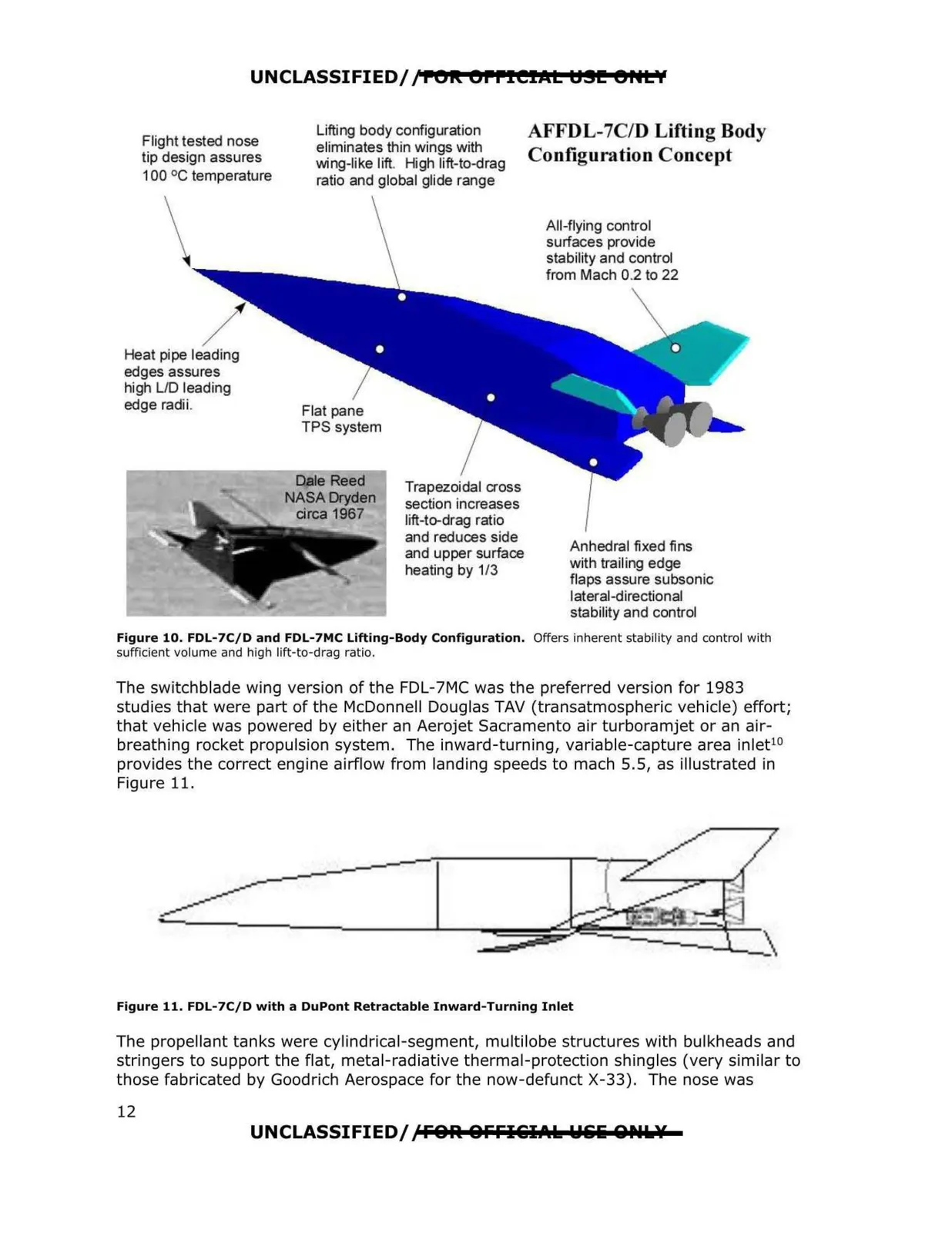
UNCLASSIFIED/ /POR: OPPIEIICL t:191!!! 9HL'I Lifting body configuration AFFDL-7C/D Lifting Body Flight tested nose eliminates thin wings with tip design assures Configuration Concept wing-like lift. High lift-to-drag 100 °C temperature ratio and global glide range All-flying control surfaces provide stability and control from Mach 02 to 22 Heat pipe leading edges assures high LID leading edge radii. Flat pane TPS system Trapezoidal cross section increases lift-to-drag ratio and reduces side Anhedral fixed fins and upper surface with trailing edge heating by 1/3 flaps assure subsonic lateral-directional stability and control Figure 10. FDL-7C/D and FDL-7MC Lifting-Body Configuration. Offers inherent stability and control with sufficient volume and high lift-to-drag ratio. The switchblade wing version of the FDL-7MC was the preferred version for 1983 studies that were part of the McDonnell Douglas TAV (transatmospheric vehicle) effort; that vehicle was powered by either an Aerojet Sacramento air turboramjet or an air breathing rocket propulsion system. The inward-turning, variable-capture area inlet10 provides the correct engine airflow from landing speeds to mach 5.5, as illustrated in Figure 11. Figure 11. FDL-7C/D with a DuPont Retractable Inward-Turning Inlet The propellant tanks were cylindrical-segment, multilobe structures with bulkheads and stringers to support the flat, metal-radiative thermal-protection shingles (very similar to those fabricated by Goodrich Aerospace for the now-defunct X-33). The nose was UNCLASSIFIED/lFOR. OFFI&I.t.k Wliliii 8Plk¥ 12