AAWSAP DIRD, Space Access: Where We’ve Been and Where We Could Go, March 2010
DOW-UAP-D124 · page 27 of 56
Text
This text came with the file. It may have mistakes. When the text and the image disagree, the image is right.
UNCLASSIFIED//EOR OEEICI0L: Pi'li ODIL:¥
On other McDonnell hypersonic configurations with all-movable control surfaces, the
interface between the fin and the body became a critical heating issue for the rotating
shaft attaching the fin to the body. This was an area of concern on this vehicle, and
specially instrumented fins were installed to measure the local heating. Again, the
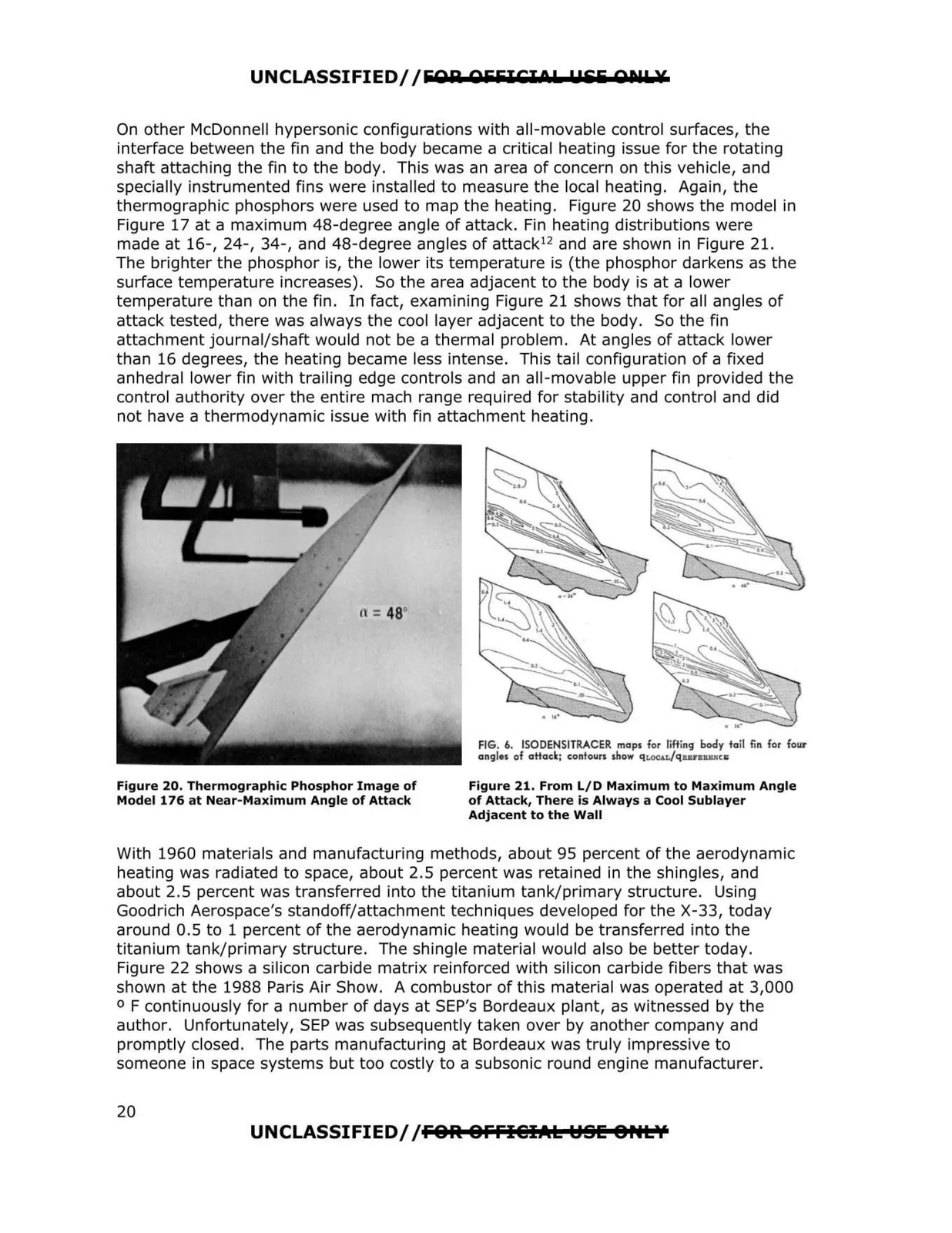
thermographic phosphors were used to map the heating. Figure 20 shows the model in
Figure 17 at a maximum 48-degree angle of attack. Fin heating distributions were
made at 16-, 24-, 34-, and 48-degree angles of attack 12 and are shown in Figure 21.
The brighter the phosphor is, the lower its temperature is (the phosphor darkens as the
surface temperature increases). So the area adjacent to the body is at a lower
temperature than on the fin. In fact, examining Figure 21 shows that for all angles of
attack tested, there was always the cool layer adjacent to the body. So the fin
attachment journal/shaft would not be a thermal problem. At angles of attack lower
than 16 degrees, the heating became less intense. This tail configuration of a fixed
anhedral lower fin with trailing edge controls and an all-movable upper fin provided the
control authority over the entire mach range required for stability and control and did
not have a thermodynamic issue with fin attachment heating.
o =48°
Figure 20. Thermographic Phosphor Image of
Model 176 at Near-Maximum Angle of Attack
FIG. 6. ISODENSITRACER maps for lifting body tail fin for four
angles ot attack; contours show qr.ocw,/qun1u,,m,
Figure 21. From L/D Maximum to Maximum Angle
of Attack, There is Always a Cool Sublayer
Adjacent to the Wall
With 1960 materials and manufacturing methods, about 95 percent of the aerodynamic
heating was radiated to space, about 2.5 percent was retained in the shingles, and
about 2.5 percent was transferred into the titanium tank/primary structure. Using
Goodrich Aerospace's standoff/attachment techniques developed for the X-33, today
around 0.5 to 1 percent of the aerodynamic heating would be transferred into the
titanium tank/primary structure. The shingle material would also be better today.
Figure 22 shows a silicon carbide matrix reinforced with silicon carbide fibers that was
shown at the 1988 Paris Air Show. A combustor of this material was operated at 3,000
° F continuously for a number of days at SEP's Bordeaux plant, as witnessed by the
author. Unfortunately, SEP was subsequently taken over by another company and
promptly closed. The parts manufacturing at Bordeaux was truly impressive to
someone in space systems but too costly to a subsonic round engine manufacturer.
UNCLASSIFIED/ /FOR. OFFI@IAL YSIE 8HL'/
20