AAWSAP DIRD, Inertial Electrostatic Confinement Fusion, March 2010
DOW-UAP-D125 · page 63 of 72
Text
This text came with the file. It may have mistakes. When the text and the image disagree, the image is right.
UNCLASSIFIED/ /FOR 8FFl@IAL ~!II! 8HLY
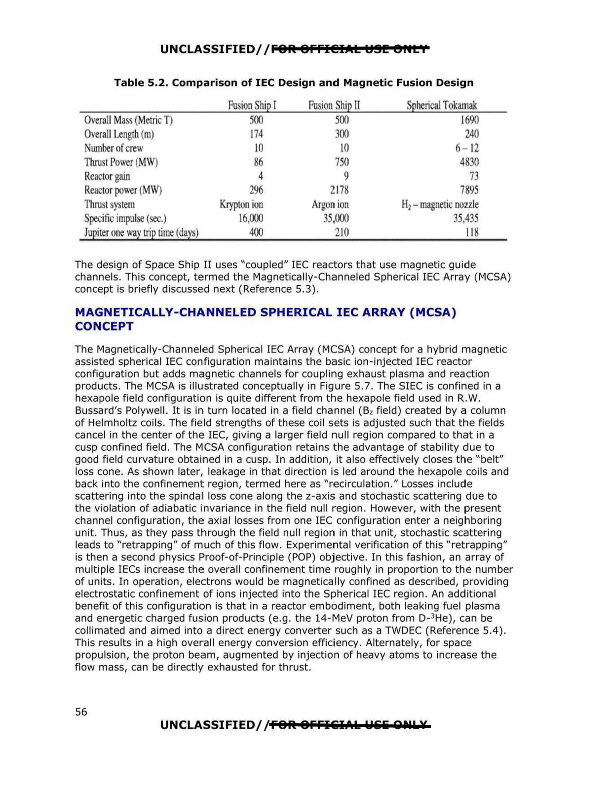
Table 5.2. Comparison of IEC Design and Magnetic Fusion Design
Pu ionShip I
r'U ion hi pII
pherical Tokamak
0 emll Mass Metric T
500
500
1690
0 emJI Length (m
174
00
240
umber ofcrew
JO
10
6- 12
Thro I P wer (MW)
750
48 0
Rea torgain
4
9
7
Rea torpower (MW)
21
217
7895
Thrust y t m
Krypt nion
Arg n ion
H1- magnetic nozzle
pecific impul
I 000
,000
5,435
Jupiter ne way trip time (day'
400
210
118
The design of Space Ship II uses "coupled" IEC reactors that use magnetic guide
channels. This concept, termed the Magnetically-Channeled Spherical IEC Array (MCSA)
concept is briefly discussed next (Reference 5.3).
MAGNETICALLY-CHANNELED SPHERICAL IEC ARRAY {MCSA)
CONCEPT
The Magnetically-Channeled Spherical IEC Array (MCSA) concept for a hybrid magnetic
assisted spherical IEC configuration maintains the basic ion-injected IEC reactor
configuration but adds magnetic channels for coupling exhaust plasma and reaction
products. The MCSA is illustrated conceptually in Figure 5.7. The SIEC is confined in a
hexapole field configuration is quite different from the hexapole field used in R.W.
Bussard's Polywell. It is in turn located in a field channel (Bz field) created by a column
of Helmholtz coils. The field strengths of these coil sets is adjusted such that the fields
cancel in the center of the IEC, giving a larger field null region compared to that in a
cusp confined field . The MCSA configuration retains the advantage of stability due to
good field curvature obtained in a cusp. In addition, it also effectively closes the "belt"
loss cone. As shown later, leakage in that direction is led around the hexapole coils and
back into the confinement region, termed here as "recirculation." Losses include
scattering into the spindal loss cone along the z-axis and stochastic scattering due to
the violation of adiabatic invariance in the field null region. However, with the present
channel configuration, the axial losses from one IEC configuration enter a neighboring
unit. Thus, as they pass through the field null reg ion in that unit, stochastic scattering
leads to "retrapping" of much of this flow. Experimental verification of this "retrapping"
is then a second physics Proof-of-Principle (POP) objective. In this fashion, an array of
multiple IECs increase the overall confinement time roughly in proportion to the number
of units. In operation, electrons would be magnetically confined as described, providing
electrostatic confinement of ions injected into the Spherical IEC region. An additional
benefit of this configuration is that in a reactor embodiment, both leaking fuel plasma
and energetic charged fusion products (e.g. the 14-MeV proton from D-3He), can be
collimated and aimed into a direct energy converter such as a TWDEC (Reference 5.4) .
This results in a high overall energy conversion efficiency. Alternately, for space
propulsion, the proton beam, augmented by injection of heavy atoms to increase the
flow mass, can be directly exhausted for thrust.
UNCLASSIFIED/ /FOR 8FFI&IAk Wliii Qr.IL¥
56