AAWSAP DIRD, Metallic Spintronics, March 2010
DOW-UAP-D129 · page 10 of 27
Text
This text came with the file. It may have mistakes. When the text and the image disagree, the image is right.
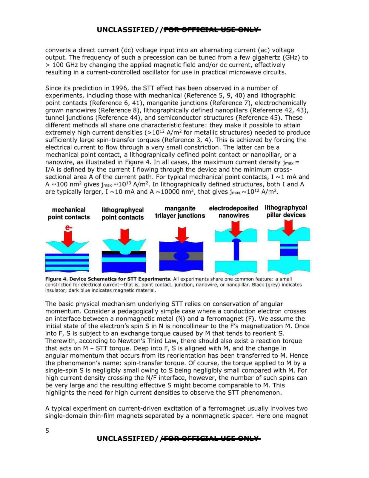
UNCLASSIFIED/ /fOft Offl@IAL ~SE 8,.L?f converts a direct current (de) voltage input into an alternating current (ac) voltage output. The frequency of such a precession can be tuned from a few gigahertz (GHz) to > 100 GHz by changing the applied magnetic field and/or de current, effectively resulting in a current-controlled oscillator for use in practical microwave circuits. Since its prediction in 1996, the STT effect has been observed in a number of experiments, including those with mechanical (Reference 5, 9, 40) and lithographic point contacts (Reference 6, 41), manganite junctions (Reference 7), electrochemically grown nanowires (Reference 8), lithographically defined nanopillars (Reference 42, 43), tunnel junctions (Reference 44), and semiconductor structures (Reference 45). These different methods all share one characteristic feature: they make it possible to attain extremely high current densities (>10 12 A/m 2 for metallic structures) needed to produce sufficiently large spin-transfer torques (Reference 3, 4 ). This is achieved by forcing the electrical current to flow through a very small constriction. The latter can be a mechanical point contact, a lithographically defined point contact or nanopillar, or a nanowire, as illustrated in Figure 4. I n all cases, the maximum current density jmax = I/A is defined by the current I flowing through the device and the minimum cross sectional area A of the current path. For typical mechanical point contacts, I ~1 mA and A ~100 nm2 gives jmax ~1013 A/m 2 . In lithographically defined structures, both I and A are typically larger, I ~10 mA and A ~10000 nm that gives jmax ~10 A/m 2 12 2 , . manganite electrodeposited IIthog raphycal mechanical lithographycal trilayer junctions nanowires pillar devices point contacts point contacts e- Figure 4. Device Schematics for STT Experiments. All experiments share one common feature: a small constriction for electrical current-that Is, point contact, junction, nanowire, or nanopillar. Black (grey) Indicates insulator; dark blue indicates magnetic material. The basic physical mechanism underlying STT relies on conservation of angular momentum. Consider a pedagogically simple case where a conduction electron crosses an interface between a nonmagnetic metal (N) and a ferromagnet (F). We assume the initial state of the electron's spin S in N is noncollinear to the F's magnetization M. Once into F, S is subject to an exchange torque caused by M that tends to reorient S. Therewith, according to Newton's Third Law, there should also exist a reaction torque that acts on M - STT torque. Deep into F, S is aligned with M, and the change in angular momentum that occurs from its reorientation has been transferred to M. Hence the phenomenon's name: spin -transfer torque. Of course, the torque applied to M by a single-spin S is negligibly small owing to S being negligibly small compared with M. For high current density crossing the N/F interface, however, the number of such spins can be very large and the resulting effective S might become comparable to M. This highlights the need for high current densities to observe the STT phenomenon. A typical experiment on current-driven excitation of a ferromagnet usually involves two single-domain thin-film magnets separated by a nonmagnetic spacer. Here one magnet UNCLASSIFIED/ ,CFOA QFFIGIAk W&& 0PtLY 5