AAWSAP DIRD, Metallic Spintronics, March 2010
DOW-UAP-D129 · page 11 of 27
Text
This text came with the file. It may have mistakes. When the text and the image disagree, the image is right.
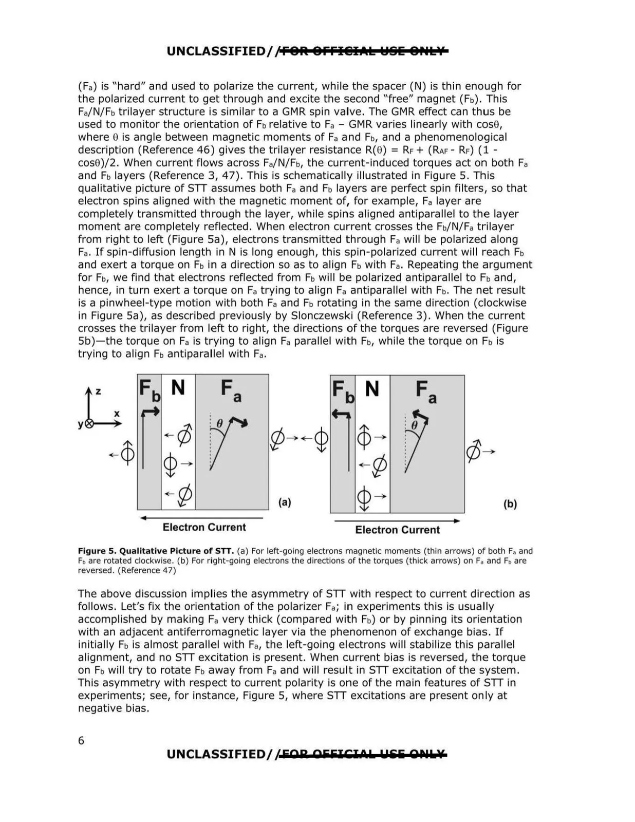
UNCLASSIFIED//FOR OFFIElIAk WSE OPtkY (Fa) is "hard" and used to polarize the current, while the spacer (N) is thin enough for the polarized current to get through and excite the second "free" magnet (Fb), This Fa/N/Fb trllayer structure is similar to a GMR spin valve. The GMR effect can thus be used to monitor the orientation of Fb relative to Fa - GMR varies linearly with cose, where e is angle between magnetic moments of Fa and Fb, and a phenomenological description (Reference 46) gives the trilayer resistance R(0) = RF+ (RAF- RF) (1 cos0)/2. When current flows across Fa/N/Fb, the current-induced torques act on both Fa and Fb layers (Reference 3, 47). This is schematically illustrated in Figure 5. This qualitative picture of STT .assumes both Fa and Fb layers are perfect spin filters, so that electron spins aligned with the magnetic moment of, for example, Fa layer are completely transmitted through the layer, while spins aligned antiparallel to the layer moment are completely reflected. When electron current crosses the Fb/N/Fatrilayer from right to left (Figure Sa), electrons transmitted t hrough Fa will be polarized along Fa. If spin-diffusion length in N is long enough, this spin-polarized current will reach Fb and exert a torque on Fb in a direction so as to align Fb with Fa. Repeating the argument for Fb, we find that electrons reflected from Fb will be polarized antiparallel to Fb and, hence, in turn exert a torque on Fa trying to align Fa antiparallel with Fb. The net result is a pinwheel-type motion with both Fa and Fb rotating in the same direction (clockwise in Figure Sa), as described previously by Slonczewski (Reference 3). When the current crosses the trilayer from left to right, the directions of the torques are reversed (Figure Sb)- the torque on Fa is trying to align Fa parallel with Fb, while the torque on Fb is trying to align Fb antiparallel with Fa . Fb N Fa F N r -¢ V ¢- ¢ (b) Electron Current Electron Current Figure 5. Qualitative Picture of STT. (a) For left-going electrons magnetic moments (thin arrows) of both Fa and Fb are rotated clockwise. (b) For right-going electrons the directions of the torques (thick arrows) on Fa and Fb are reversed. (Reference 47) The above discussion implies the asymmetry of STT with respect to current direction as follows. Let's fix the orientation of the polarizer Fa; in experiments this is usually accomplished by making Fa very thick (compared wit h Fb) or by pinning its orientation with an adjacent antiferromagnetic layer via the phenomenon of exchange bias. If initially Fb is almost parallel with Fa, the left-going electrons will stabilize this parallel alignment, and no STT excitation is present. When current bias is reversed , the torque on Fb will try to rotate Fb away from Fa and will result in STT excitation of the system. This asymmetry with respect to current polarity is one of the main features of STT in experiments; see, for instance, Figure 5, where STT excitations are present only at negative bias. UNCLASSIFIED/ ,'EAR AEFICIOL !9&i Ql'IL¥ 6