AAWSAP DIRD, Metallic Spintronics, March 2010
DOW-UAP-D129 · page 13 of 27
Text
This text came with the file. It may have mistakes. When the text and the image disagree, the image is right.
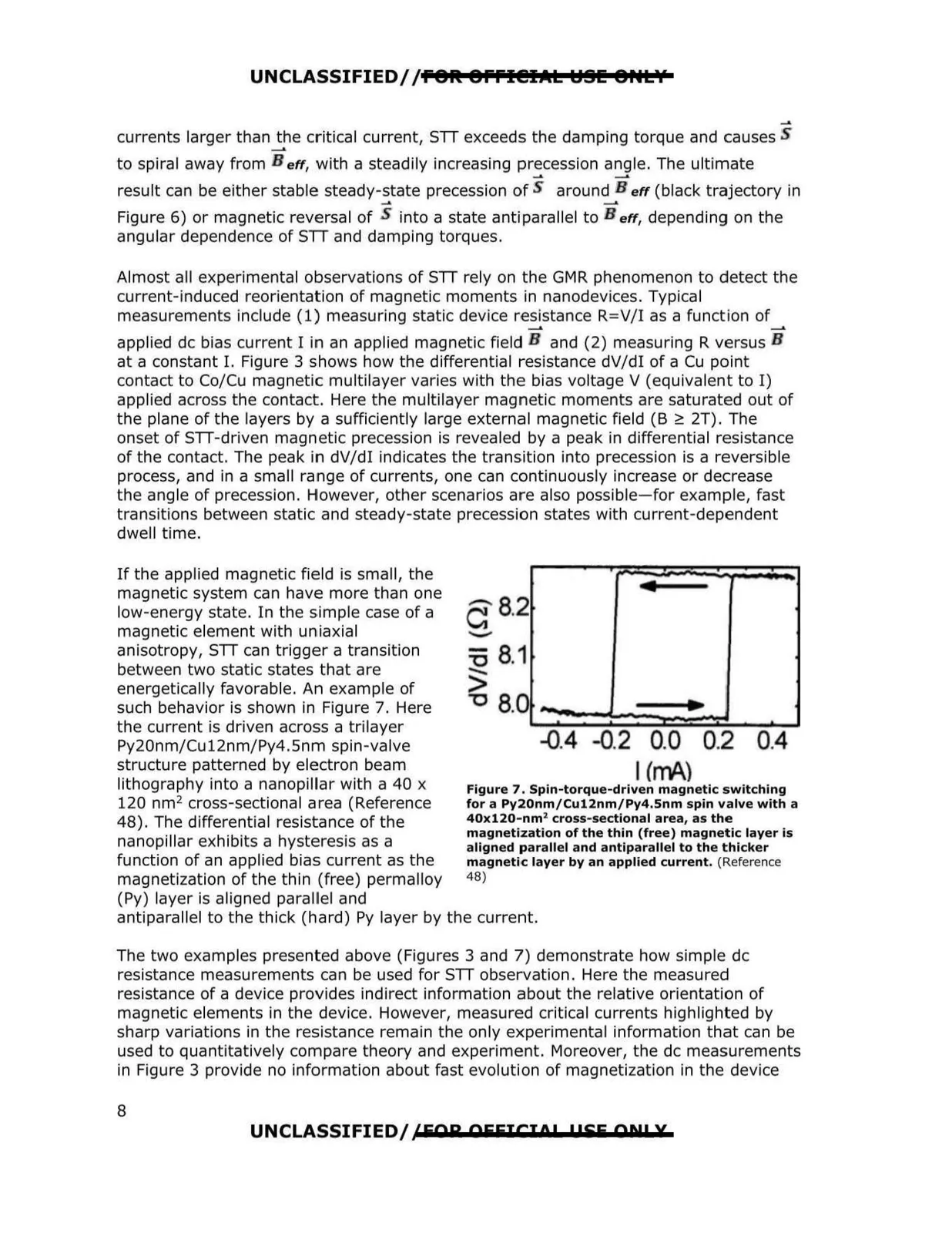
-- UNCLASSIFIED//fOlt Offl@IAL ~91! OHL¥ currents larger than the critical current, STT exceeds the damping torque and causes __. to spiral away from B eff, with a steadily increasing precession angle. The ultimate ... __. result can be either stable steady-state precession of S around B eff (black trajectory in ... Figure 6) or magnetic reversal of S into a state anti parallel to B eff, depending on the angular dependence of STT and damping torques. Almost all experimental observations of STT rely on the GMR phenomenon to detect the current-induced reorientation of magnetic moments in nanodevices. Typical measurements include (1) measuring static device resistance R=V/I as a function of __. __. applied de bias current I in an applied magnetic field B and (2) measuring R versus B at a constant I. Figure 3 shows how the differential resistance dV/dl of a Cu point contact to Co/Cu magnetic multilayer varies with the bias voltage V (equivalent to I) applied across the contact. Here the multilayer magnetic moments are saturated out of the plane of the layers by a sufficiently large externa l magnetic field (B ;:: 2T). The onset of STT-driven magnetic precession is revealed by a peak in differential resistance of the contact. The peak in dV/dl indicates the transition into precession is a reversible process, and in a small range of currents, one can continuously increase or decrease the angle of precession. However, other scenarios are also possible- for example, fast transitions between static and steady-state precession states with current-dependent dwell time. If the applied magnetic field is small, the magnetic system can have more than one • low-energy state. In the simple case of a 6 a.2 magnetic element with uniaxial anisotropy, STT can trigger a transition =a 8.1 between two static states that are energetically favorable. An example of > . such behavior is shown in Figure 7. Here u 8.0 • the current is driven across a trilayer Py20nm/Cu12nm/Py4.Snm spin-valve -0.4 -0.2 0.0 0.2 0.4 structure patterned by electron beam I (mA.) lithography into a nanopillar with a 40 x Figure 7. Spin-torque-driven magnetic switching 120 nm 2 cross-sectional area (Reference for a Py20nm/Cu12nm/Py4.5nm spin valve with a 40x120-nm 2 cross-sectional area, as the 48). The differential resistance of the magnetization of the thin (free) magnetic layer is nanopillar exhibits a hysteresis as a aligned parallel and antiparallel to the thicker function of an applied bias current as the magnetic layer by an applied current. (Reference magnetization of the thin (free) permalloy 48) (Py) layer is aligned parallel and antiparallel to the thick (hard) Py layer by the current. The two examples presented above (Figures 3 and 7) demonstrate how simple de resistance measurements can be used for STT observation. Here the measured resistance of a device provides indirect information about the relative orientation of magnetic elements in the device. However, measured critical currents highlighted by sharp variations in the resistance remain the only experimental information that can be used to quantitatively compare theory and experiment. Moreover, the de measurements in Figure 3 provide no information about fast evolution of magnetization in the device 8 UNCLASSIFIED/ /FOR OFFICIO 1 1!SF Al:!! X